Method for creating tensile strain by applying stress memorization techniques at close proximity to the gate electrode

a stress memorization and gate electrode technology, applied in the field of integrated circuit fabrication, to achieve the effect of reducing strain, avoiding or suppressing volume reduction, and enhancing the performance of n-channel transistors

Active Publication Date: 2009-10-01
GLOBALFOUNDRIES US INC
View PDF14 Cites 15 Cited by
  • Summary
  • Abstract
  • Description
  • Claims
  • Application Information

AI Technical Summary

Benefits of technology

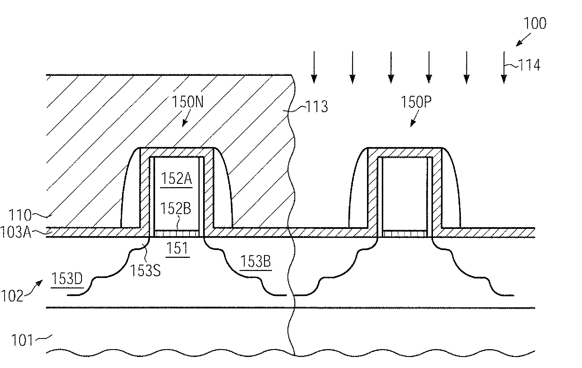
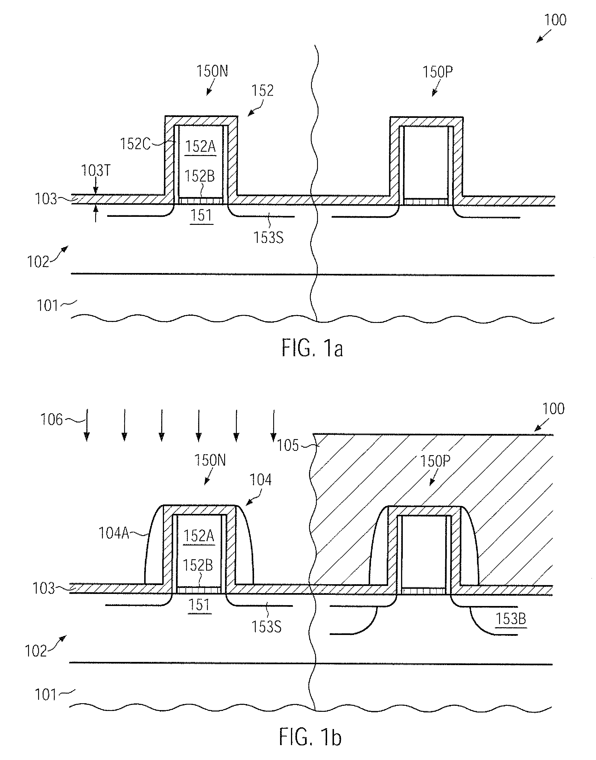
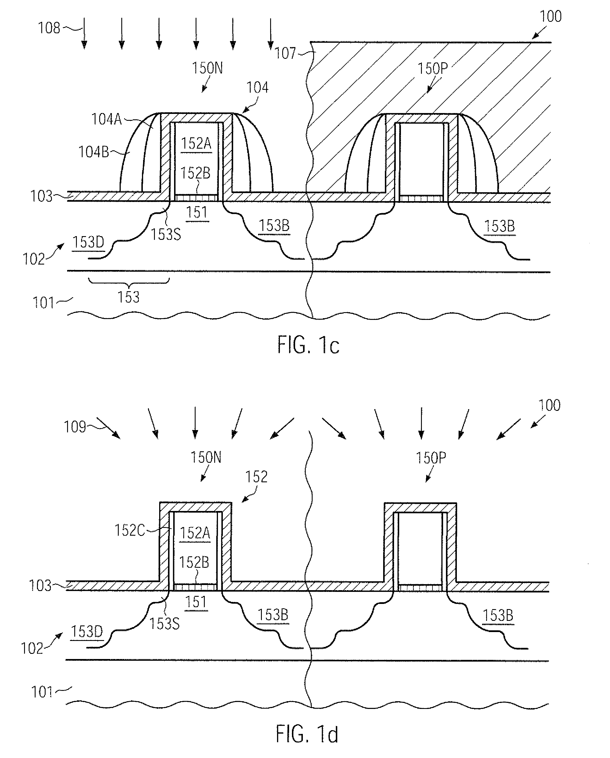
[0013]The present disclosure relates to techniques for forming advanced semiconductor devices in which performance of N-channel transistors may be enhanced on the basis of stress memorization techniques by improving the conditions during the re-growth of heavily damaged drain and source areas. Without intending to restrict the present application to the following explanation, it is believed that the presence of the sidewall spacer elements during the anneal process on the basis of the rigid surface layer may have a negative effect on the strained re-crystallization of the drain and source regions. That is, after forming one or two spacer elements and using the same as an implantation mask, in particular during the high energy and dose implantation process for forming the buffer regions and the deep drain and source regions, significant damage may also be created in the spacer elements, thereby possibly affecting their capability of avoiding or suppressing a reduction in volume upon the re-crystallization process. Consequently, a modified strain state of the drain and source areas positioned between the channel region and the deep drain and source regions may re-grow with a less pronounced strain, thereby also reducing the overall strain transfer mechanism obtained by the re-crystallized deep drain and source regions, which may have a high offset to the channel region corresponding to the width of the previously used spacer elements. According to illustrative aspects disclosed herein, one or more spacer elements may be removed prior to the deposition of the rigid surface material, so that the strained re-crystallized state of the drain and source regions may be positioned closer to the channel region, thereby enhancing the overall strain-inducing mechanism.

Problems solved by technology

That is, after forming one or two spacer elements and using the same as an implantation mask, in particular during the high energy and dose implantation process for forming the buffer regions and the deep drain and source regions, significant damage may also be created in the spacer elements, thereby possibly affecting their capability of avoiding or suppressing a reduction in volume upon the re-crystallization process.

Method used


Image

  • Method for creating tensile strain by applying stress memorization techniques at close proximity to the gate electrode
  • Method for creating tensile strain by applying stress memorization techniques at close proximity to the gate electrode
  • Method for creating tensile strain by applying stress memorization techniques at close proximity to the gate electrode

Examples


Embodiment Construction

[0023]Various illustrative embodiments are described below. In the interest of clarity, not all features of an actual implementation are described in this specification. It will of course be appreciated that in the development of any such actual embodiment, numerous implementation-specific decisions must be made to achieve the developers' specific goals, such as compliance with system-related and business-related constraints, which will vary from one implementation to another. Moreover, it will be appreciated that such a development effort might be complex and time-consuming, but would nevertheless be a routine undertaking for those of ordinary skill in the art having the benefit of this disclosure.

[0024]The present subject matter will now be described with reference to the attached figures. Various structures, systems and devices are schematically depicted in the drawings for purposes of explanation only and so as to not obscure the present disclosure with details that are well kno...


PUM


Abstract

After forming the outer drain and source regions of an N-channel transistor, the spacer structure may be removed on the basis of an appropriately designed etch stop layer so that a rigid material layer may be positioned more closely to the gate electrode, thereby enhancing the overall strain-inducing mechanism during a subsequent anneal process in the presence of the material layer and providing an enhanced stress memorization technique (SMT). In some illustrative embodiments, a selective SMT approach may be provided.

Description

BACKGROUND[0001]1. Field of the Disclosure[0002]Generally, the present disclosure relates to the fabrication of integrated circuits, and, more particularly, to the formation of transistors having strained channel regions by using stress-inducing sources to enhance charge carrier mobility in the channel region of a MOS transistor.[0003]2. Description of the Related Art[0004]Generally, a plurality of process technologies are currently practiced to fabricate integrated circuits, wherein, for complex circuitry, such as microprocessors, storage chips and the like, CMOS technology is currently one of the most promising approaches due to the superior characteristics in view of operating speed and / or power consumption and / or cost efficiency. During the fabrication of complex integrated circuits using CMOS technology, millions of transistors, i.e., N-channel transistors and P-channel transistors, are formed on a substrate including a crystalline semiconductor layer. A MOS transistor, irrespe...

Claims


Application Information

Patent Timeline
Patent Type & Authority Applications(United States)
IPC IPC(8): H01L21/336
CPCH01L21/26513H01L21/823807H01L21/823814H01L29/7847H01L29/665H01L29/6653H01L29/6659H01L21/823864
Inventor GEHRING, ANDREASMOWRY, ANTHONYWEI, ANDY
Owner GLOBALFOUNDRIES US INC
Why Eureka
Try Eureka