
Trash can restrict top

a trash can and top technology, applied in the field of trash cans, can solve the problems of short product life, inefficient mechanism, and affecting the use of trash cans,

Inactive Publication Date: 2007-04-26
J F MESKILL ENTERPRISES
View PDF40 Cites 76 Cited by
  • Summary
  • Abstract
  • Description
  • Claims
  • Application Information

AI Technical Summary

Problems solved by technology

Conventional trash containers suffer from several drawbacks such as inefficient mechanisms, short product life, and the like.
Such difficulties can be caused by inadequate and / or poor design.

Method used


Image

  • Trash can restrict top
  • Trash can restrict top
  • Trash can restrict top

Examples


Embodiment Construction

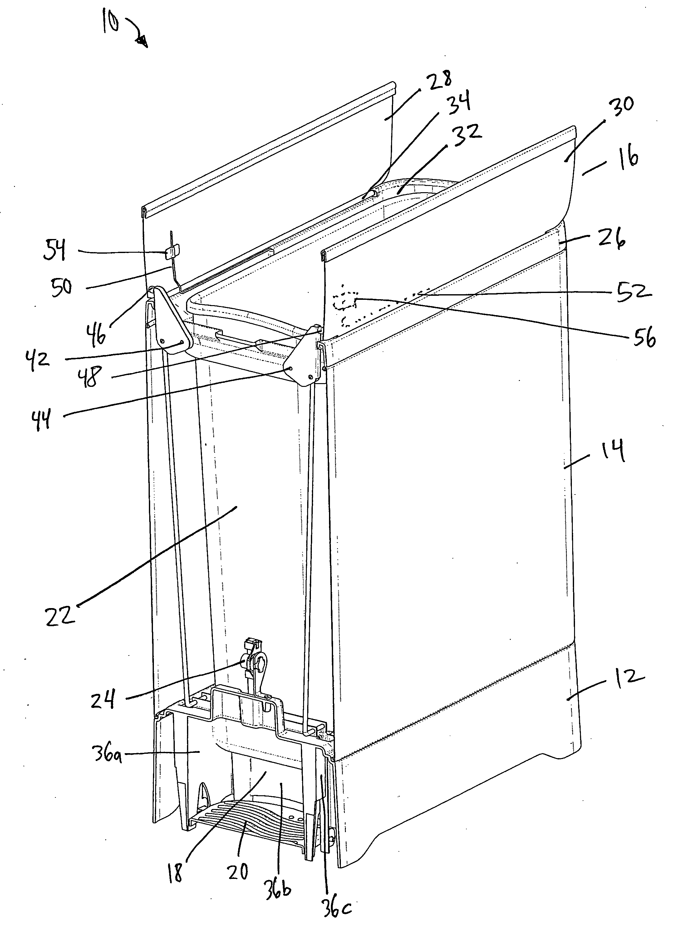
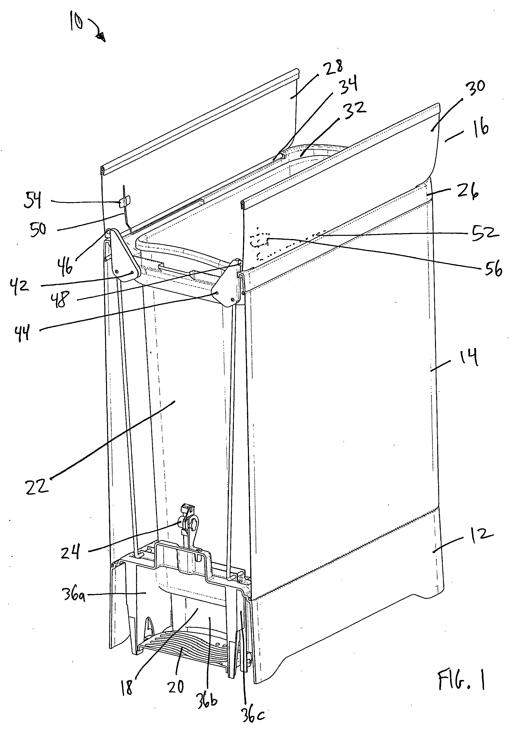
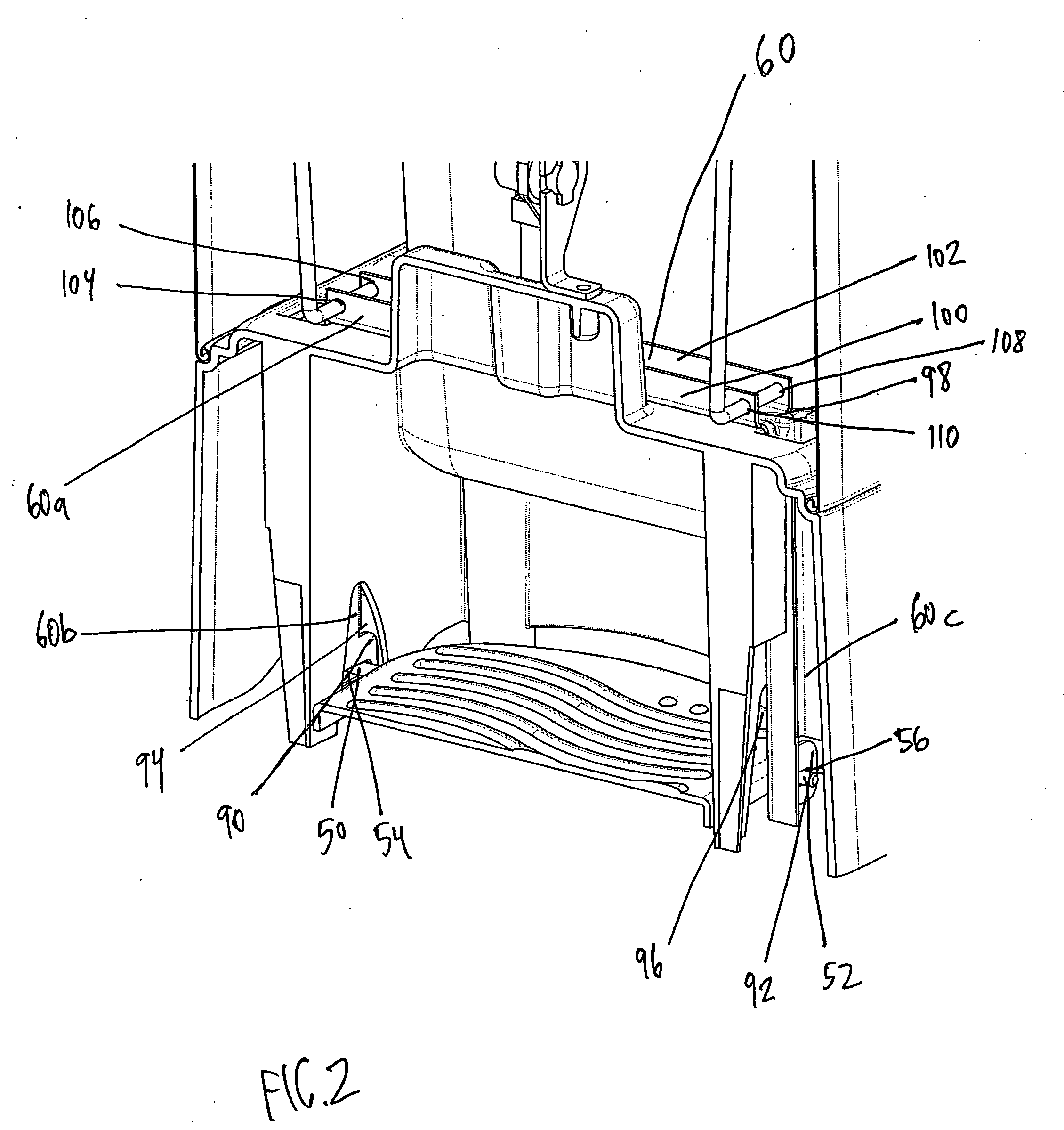
[0012]FIG. 1 illustrates a perspective view of a trash can 10. The front of the trash can 10 is cut away in FIG. 1 to display the mechanism for opening the trash can 10. The trash can 10 comprises a base 12, a body 14 and a top 16 which are permanently fixed together. The base 12 is employed to support the structure of the trash can 10 and to insure that such support is level. The base 12 is comprised of two side walls oriented substantially in parallel to one another, a rear wall and a front. The base 12 is a molded plastic structure. In order to provide greater support, the side walls of the base can be angled (e.g., 5-30 degrees) outward from the top of the side wall such that the base 12 is flared in relation to the body 14 of the trash can 10. Each side of the bottom of the base 12 has a middle portion cut-out to provide access to the bottom of the base for cleaning and maintenance and to allow the trash can to sit on uneven surfaces. The base 12 also includes a rear wall (not ...


PUM


Abstract

The subject invention relates to a trash can that comprises a base and a liner supported by the base to receive and store trash. A body, supported by the base, houses the liner and a top comprising a support wall supported by the body and two doors rotatably supported by said top support wall, wherein each door is hinged on one side to said support wall. At least one L-shaped bracket is positioned against one top door and connected to the body via a pin. At least one lift rod with a first end operatively connected to each of the L-shaped brackets. A lift bar interfaces with a second end of each of the two lift rods. A pedal mechanically connected to the lift bar moves the lift bar in a downward motion to pull the lift rods down thereby rotating the L-shaped bracket about the pin to extend each L-shaped bracket in an upward motion to open each top door.

Description

BACKGROUND OF THE INVENTION [0001] Trash containers are conventionally manufactured utilizing various materials such as plastic, aluminum, stainless steel and the like. The size of such containers can vary based on the location and use of the container. For example, a trash container located in a public park may be large and made of heavy material such as stone or cement with a large opening for trash. Alternatively, a trash container in an office may be made of a lightweight material such as plastic and be relatively small in size. [0002] Due to the nature of the disparate environments in which a trash container is located, features of the trash containers can differ. In one environment, such as a restaurant, a swing top may be preferred whereas in a restroom a lift top lid is appropriate. In addition, the trash container can be stationary (e.g., on legs, flat bottom, etc.) or mobile, such as on wheels, to conveniently locate the trash container as desired. [0003] Conventional tras...

Claims


Application Information

Patent Timeline
IPC IPC(8): B65D43/26
CPCB65F1/08B65F1/163B65F2001/1661
Inventor KALMAN, JEFFREYSAUNDERS, CRAIG
Owner J F MESKILL ENTERPRISES
Learn More