Liquid crystal display device

a liquid crystal display and display device technology, applied in non-linear optics, instruments, optics, etc., can solve the problems of reducing the angle of field, difficulty in watching images, and large variation in brightness, color and contrast, etc., to achieve excellent antireflection properties, excellent contrast, and uniform display of images

Active Publication Date: 2007-04-26
ZEON CORP
View PDF24 Cites 30 Cited by
  • Summary
  • Abstract
  • Description
  • Claims
  • Application Information

AI Technical Summary

Benefits of technology

[0010] The present invention has an object of providing a liquid crystal display device which exhibits excellent antireflection property, scratch resistance and durability, provides a wide angle of field and achieves uniform display of images with great contrast at any angle of observation.

Problems solved by technology

It has been pointed out that liquid crystal display devices have a drawback in that brightness, color and contrast vary to a great extent and difficulty arises in watching images when the images are observed at oblique angles.
However, in accordance with this technology, the arrangement of polarizer plates shifts from the cross-nichol arrangement depending on the angle of observation, and this causes a decrease in the angle of field due to leak of light although the decrease in the angle of field due to the liquid crystal molecules in the liquid crystal cell is relatively suppressed.
However, none of these means are sufficient for providing a liquid crystal display device which exhibits uniform display of images with a great contrast at any angle of observation, and further improvement has been desired.

Method used


Image

  • Liquid crystal display device
  • Liquid crystal display device
  • Liquid crystal display device

Examples


first embodiment

(I-1) the Preferable Arrangement

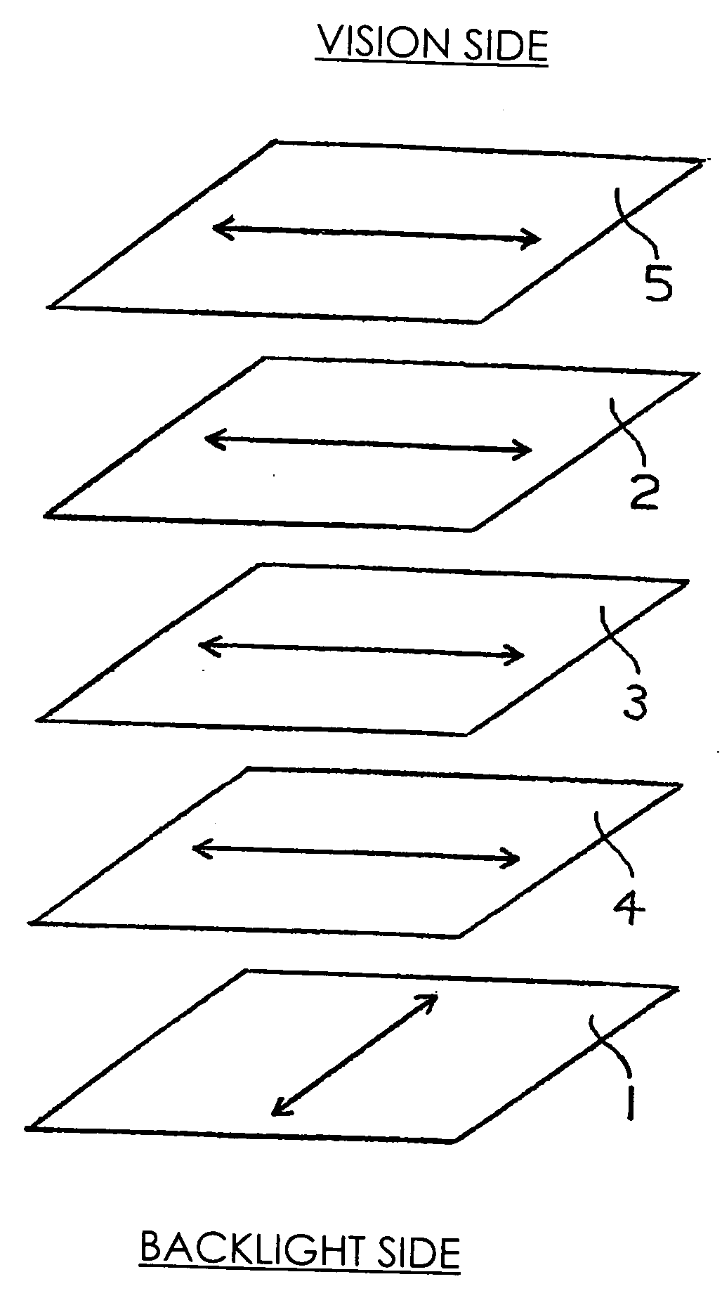
[0158]FIG. 3 shows a diagram exhibiting the first embodiment of the preferable arrangement (referred to as arrangement I-1, hereinafter) of the liquid crystal display device of the present invention. In arrangement I-1, the absorption axis of the polarizer at the output side and the in-plane slow axis of the liquid crystal of the liquid crystal cell under application of no voltage are disposed at relative positions parallel to each other, and the absorption axis of the polarizer at the output side and the in-plane slow axis of the liquid crystal of the liquid crystal cell under application of no voltage are disposed at relative positions parallel to each other. The in-plane slow axes of optically anisotropic member (A) and optically anisotropic member (B) are disposed at relative positions approximately parallel to each other. It is preferable that the in-plane slow axis of optically anisotropic member (B) and the in-plane slow axis of the liquid crys...

second embodiment

(I-2) the Preferable Arrangement

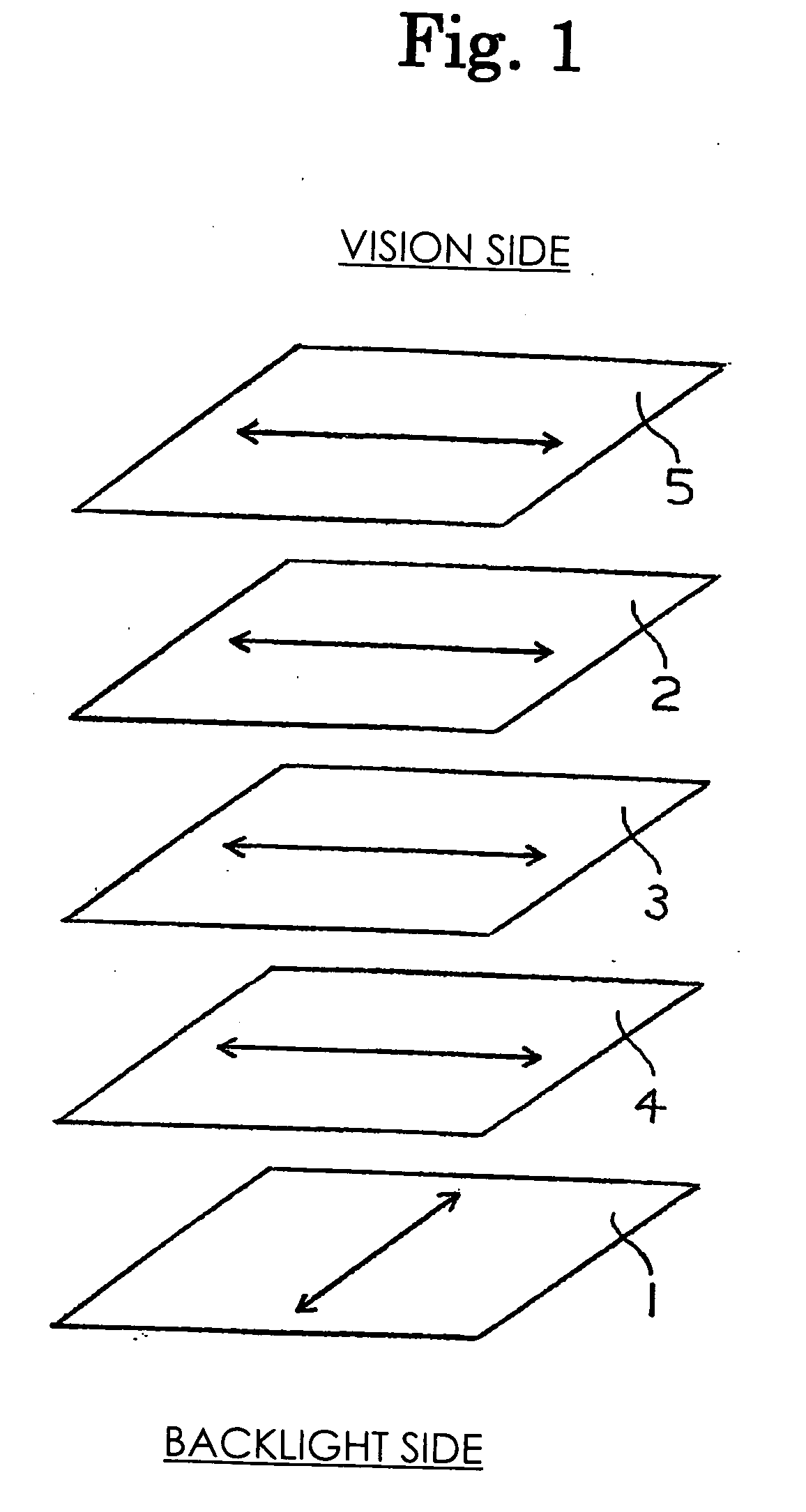
[0161]FIG. 4 shows a diagram exhibiting the second embodiment of the preferable arrangement (referred to as arrangement I-2, hereinafter) of the liquid crystal display device of the present invention. In arrangement I-2, the absorption axis of the polarizer at the output side and the in-plane slow axis of the liquid crystal of the liquid crystal cell under application of no voltage are disposed at relative positions parallel to each other, and the absorption axis of the polarizer at the output side and the in-plane slow axis of the liquid crystal of the liquid crystal cell under application of no voltage are disposed at relative positions parallel to each other. The in-plane slow axes of optically anisotropic member (A) and optically anisotropic member (B) are disposed at relative positions approximately parallel to each other. It is preferable that the in-plane slow axis of optically anisotropic member (B) and the in-plane slow axis of the liquid cry...

third embodiment

(II-1) the Preferable Arrangement

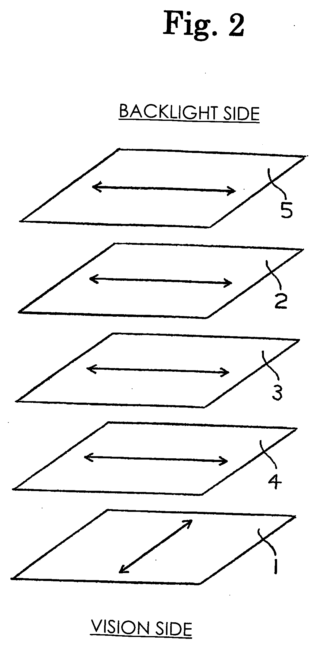
[0164]FIG. 5 shows a diagram exhibiting the third embodiment of the preferable arrangement (referred to as arrangement II-1, hereinafter) of the liquid crystal display device of the present invention. In arrangement II-1, the absorption axis of the polarizer at the output side and the in-plane slow axis of the liquid crystal of the liquid crystal cell under application of no voltage are disposed at relative positions parallel to each other, and the absorption axis of the polarizer at the output side and the in-plane slow axis of the liquid crystal of the liquid crystal cell under application of no voltage are disposed at relative positions parallel to each other. The in-plane slow axes of optically anisotropic member (A) and optically anisotropic member (B) are disposed at relative positions approximately parallel to each other. It is preferable that the in-plane slow axis of optically anisotropic member (B) and the in-plane slow axis of the liquid c...


PUM

PropertyMeasurementUnit
thicknessaaaaaaaaaa
average oblique angleaaaaaaaaaa
oblique angleaaaaaaaaaa

Abstract

A liquid crystal display device of an in-plane switching mode comprises at least optically anisotopic members (A) and (B) and liquid crystal cell disposed between a pair of polarizers having absorrption axes disposed approximately perpendicularly to each other, wherein nzA>nyA and nxB>nzB (nxA, nxB: refractive indices (n) in the direction of the in-plane slow axis; nyA, nyB: n in the in-plane direction perpendicular to the above direction; nzA, nzB: n in the direction of thickness, each at 550 nm); the in-plane slow axes of (A) and (B) are approximately parallel or perpendicular to each other; and the in-plane slow axis of (A) is approximately parallel or perpendicular to the absorption axis of a polarizer closer to (A). The antireflection property, scratch resistance and durability are exellent, the angle of field is wide, and uniform display of images with great contrast can be achieved at any angle of observation.

Description

TECHNICAL FIELD [0001] The present invention relates to a liquid crystal display device. More particularly, the present invention relates to a liquid crystal display device which exhibits excellent antireflection property, scratch resistance and durability, provides a wide angle of field and achieves uniform display of images with great contrast at any angle of observation. BACKGROUND ART [0002] Liquid crystal display devices are characterized by the high quality of images, the small thickness, the light weight and the small consumption of electric power and widely used for televisions, personal computers and automobile navigators. It has been pointed out that liquid crystal display devices have a drawback in that brightness, color and contrast vary to a great extent and difficulty arises in watching images when the images are observed at oblique angles. [0003] To overcome the drawback, improvements in the design of the liquid crystal cell itself have been studied, and a liquid crys...

Claims


Application Information

Patent Timeline
Patent Type & Authority Applications(United States)
IPC IPC(8): G02F1/1335G02F1/13363G02F1/1343
CPCG02F1/133528G02F1/13363G02F2413/13G02F2413/02G02F2413/11G02F1/134363G02F1/133634G02F1/1335
Inventor ITADANI, MOTOHIROOKUDE, SHUHEIYAMANAKA, SHUNSUKEARAKAWA, KOHEI
Owner ZEON CORP
Why Eureka
Try Eureka