
Circularly polarizing plate

a technology of polarizing plate and polarizing plate, applied in the direction of film/foil adhesives without carriers, film/foil adhesives, instruments, etc., can solve the problems of ambient light reflection or background reflection, wiring, and the inability to obtain excellent reflection hue, so as to prevent a reduction in brightness of brightness, widen the color gamut of image display apparatus, and excellent anti-reflection characteristics

Inactive Publication Date: 2020-11-12
NITTO DENKO CORP
View PDF0 Cites 0 Cited by
  • Summary
  • Abstract
  • Description
  • Claims
  • Application Information

AI Technical Summary

Benefits of technology

[0021]According to the present invention, the circularly polarizing plate excellent in antireflection characteristic can be obtained by forming the colored layer. In addition, the circularly polarizing plate of the present invention can output light having a neutral hue through the adjustment of its reflection hue by appropriate setting of the absorption wavelength of the colored layer. Further, the use of the circularly polarizing plate of the present invention can widen the color gamut of the image display apparatus while preventing a reduction in brightness thereof.

Problems solved by technology

Along with the increase, a problem, such as ambient light reflection or background reflection, due to the display apparatus itself or a reflector used in the display apparatus, such as a touch panel portion, a glass substrate, or metal wiring, has been occurring.
When a circularly polarizing plate including a retardation film having such flat wavelength dispersion characteristic is used in a display apparatus, a problem in that an excellent reflection hue is not obtained occurs.
However, the use of the retardation film having a reverse wavelength dispersion characteristic is disadvantageous in terms of cost.
In addition, when the film is applied to a reflector having a high reflectance, a problem in that it is particularly difficult to adjust the hue of the reflector occurs.

Method used


Image

  • Circularly polarizing plate
  • Circularly polarizing plate
  • Circularly polarizing plate

Examples


example 1

(i) Production of Retardation Layer (λ / 4 Plate)

[0114]Polymerization was performed by using a batch polymerization apparatus formed of two vertical reactors each including a stirring blade and a reflux condenser controlled to 100° C. 9,9-[4-(2-Hydroxyethoxy)phenyl]fluorene (BHEPF), isosorbide (ISB), diethylene glycol (DEG), diphenyl carbonate (DPC), and magnesium acetate tetrahydrate were loaded into a first reactor so that a molar ratio “BHEPF / ISB / DEG / DPC / magnesium acetate” became 0.348 / 0.490 / 0.162 / 1.005 / 1.00×10⁻⁵. After air in the reactor had been sufficiently purged with nitrogen (oxygen concentration: from 0.0005 vol % to 0.001 vol %), a temperature in the reactor was warmed with a heating medium, and stirring was started at the time point when the internal temperature became 100° C. 40 Minutes after the start of the temperature increase, the internal temperature was caused to reach 220° C., and such control that the temperature was held was performed. Simultaneously with the con...


PUM

PropertyMeasurementUnit
wavelength bandaaaaaaaaaa
visible light reflectanceaaaaaaaaaa

Abstract

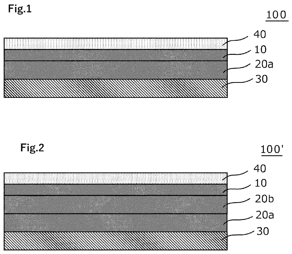
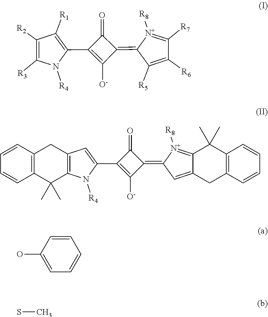
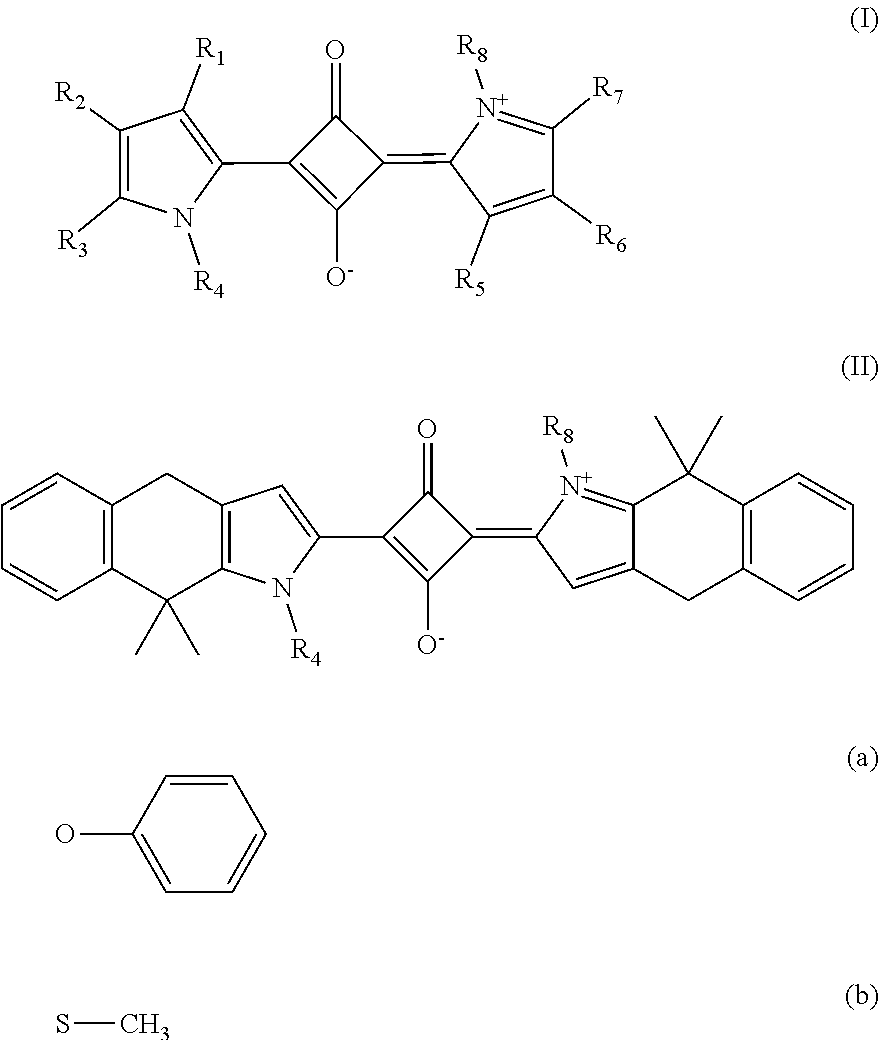
Provided is a circularly polarizing plate that is excellent in antireflection characteristic, and that can be produced at low cost. The circularly polarizing plate of the present invention includes in the stated order: a polarizer; a retardation layer (20a) configured to function as a λ / 4 plate; and a colored layer, wherein an angle formed by an absorption axis of the polarizer and a slow axis of the retardation layer (20a) is from 35° to 55°, wherein the colored layer has an absorption peak in a wavelength band in a range of from 580 nm to 610 nm, and wherein the colored layer contains a compound X represented by the general formula (I) or the general formula (II).

Description

TECHNICAL FIELD[0001]The present invention related to a circularly polarizing plate.BACKGROUND ART[0002]In recent years, the number of opportunities for a smart device typified by a smartphone and a display apparatus, such as a digital signage or a window display, to be used under strong ambient light has been increasing. Along with the increase, a problem, such as ambient light reflection or background reflection, due to the display apparatus itself or a reflector used in the display apparatus, such as a touch panel portion, a glass substrate, or metal wiring, has been occurring. In view of the foregoing, it has been known that such phenomenon is prevented by arranging a circularly polarizing plate including a λ / 4 plate on the viewer side of the apparatus. A circularly polarizing plate obtained as described below has been known as a general circularly polarizing plate. A retardation film (typically a λ / 4 plate) typified by a cycloolefin (COP)-based resin film is laminated so that i...

Claims


Application Information

Patent Timeline
Patent Type & Authority Applications(United States)
IPC IPC(8): G02F1/1335G02F1/13363
CPCG02F1/133536G02F2202/28G02F2001/133638G02F2001/133541G02F1/133634G02F1/133533C07D207/44C07D209/12C07D209/44C07D209/52C07D209/60C09K11/06C09B57/007G02B5/223H10K99/00C07D403/08G02F1/133509G02F1/133528H01L33/50G02F1/133541G02F1/133638C09K2323/031C09K2323/03C07D207/00C07D209/00C07D403/00C09J7/385C09J7/10C09J2301/408C09J2301/302C09J11/06C09J2203/318C09J2429/008C09J2433/00C09J7/20C09J2301/312G02F1/133302G02B1/10
Inventor NAKAMURA, KOZOWANG, PENGWELCH, MICHAELZHENG, SHIJUN
Owner NITTO DENKO CORP
Learn More