Method for testing the integrity of a communication cable

a communication cable and integrity technology, applied in the field of testing the integrity of communication cables, can solve the problems of long process, high cost, and prone to errors

Inactive Publication Date: 2007-05-24
SBC KNOWLEDGE VENTURES LP
View PDF8 Cites 27 Cited by
  • Summary
  • Abstract
  • Description
  • Claims
  • Application Information

AI Technical Summary

Problems solved by technology

For obvious reasons this process is

Method used


Image

  • Method for testing the integrity of a communication cable
  • Method for testing the integrity of a communication cable
  • Method for testing the integrity of a communication cable

Examples


Embodiment Construction

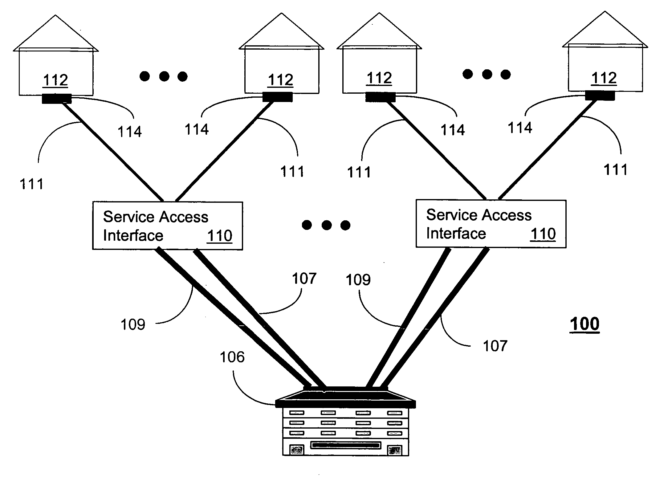
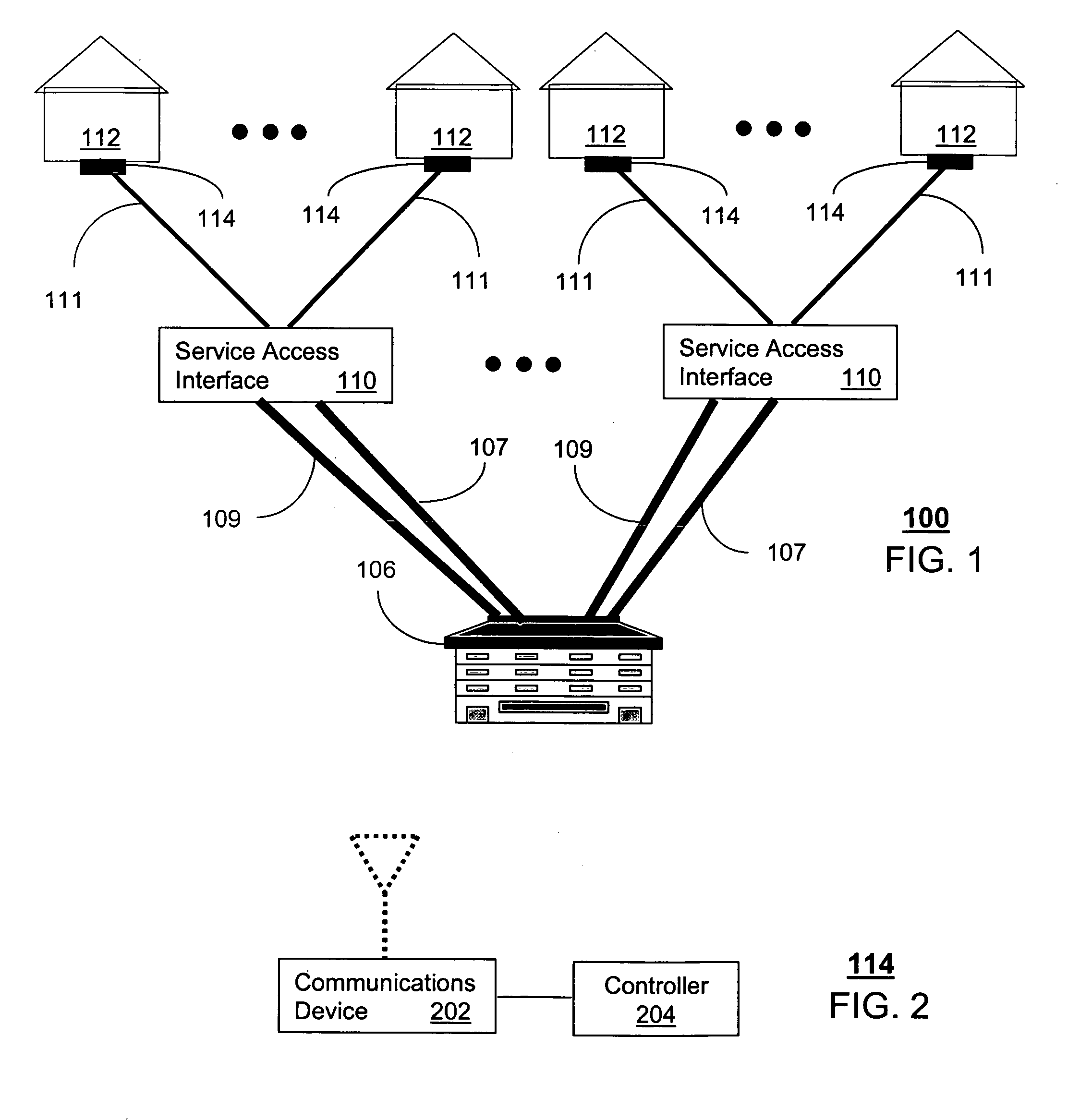
[0009]FIG. 1 is a block diagram of power and communication cabling between a central office (CO) 106 and a service access interface (SAI) 110 according to teachings of the present disclosure. The CO 106 distributes telecommunication services by way of the SAI 110 to buildings 112 (such as dwellings or commercial enterprises). For illustration purposes only, buildings 112 will be referred to herein as residences 112. Telecommunication services of the CO 106 can include traditional POTS (Plain Old Telephone Service) and broadband services such as HDTV, DSL, VoIP (Voice over Internet communications, IPTV (Internet Protocol Television), Internet services, and so on.

[0010] Links 107 are twisted copper pairs for distributing power to the SAIs 110. Alternatively, links 107 can be coupled to local commercial power near the SAIs 110 supplied by, for example, a utility company. The SAI 106 can be coupled to optical and / or electrical cables 109 from the CO 106, which carry any one or more of ...


PUM


Abstract

A method is disclosed for testing the integrity of a communication cable. A method that incorporates teachings of the present disclosure may include, for example, a smart network interface (SNI) (114) has a communications device (202) located at a building (112) and coupled to a portion (111) of a cable (109) of a communications network (100), and a controller (204). The controller is programmed to intercept (308) a request to test the cable, and perform (310, 312, 314) an integrity test on the cable according to said request.

Description

FIELD OF THE DISCLOSURE [0001] The present disclosure relates generally to testing telecommunication cables, and more specifically to a method for testing the integrity of a communication cable. BACKGROUND [0002] Splicing (the process of joining two ends) is a common practice used during installation and / or repair of communication cables. Typically, a large number of residential and / or commercial communication lines are bundled in one cable. It is not uncommon, for example, for a single cable to support hundreds if not thousands of consumers. Therefore, validating the integrity of a spliced cable is critically important. [0003] To validate a spliced cable, testing is typically performed by a manual procedure such as originating a POTS (Plain Old Telephone Service) call on each line. For obvious reasons this process is lengthy, costly, and prone to error. [0004] A need therefore arises for a method for enhanced testing of communication cables.BRIEF DESCRIPTION OF THE DRAWINGS [0005]F...

Claims


Application Information

Patent Timeline
IPC IPC(8): H04M1/24H04M3/08H04M3/22
CPCH04M1/24H04M3/08H04M3/301
Inventor GONSALVES, BRIANCHEN, ZESEN
Owner SBC KNOWLEDGE VENTURES LP
Why Eureka
Try Eureka