
Air bag module

Inactive Publication Date: 2007-05-31
HYUNDAI MOBIS CO LTD
View PDF42 Cites 40 Cited by
  • Summary
  • Abstract
  • Description
  • Claims
  • Application Information

AI Technical Summary

Benefits of technology

[0014] The present invention is directed to solve the prior art problems, and has for its object to provide an air bag module which is improved in OOP capability by suppressing the initial deployment of a cushion by a force of gradually tearing tear lines of flaps by an expansion pressure of the cushion when an expanding gas is supplied to the cushion.

Problems solved by technology

This makes it difficult to tune a friction force of the first and second flaps 8 and 9 and test the performance therefore, and it is difficult to prevent a punch-out force phenomenon entirely.

Method used


Image

  • Air bag module
  • Air bag module
  • Air bag module

Examples


Embodiment Construction

[0026] Hereinafter, preferred embodiments of the present invention will now be described in detail with reference to the accompanying drawings.

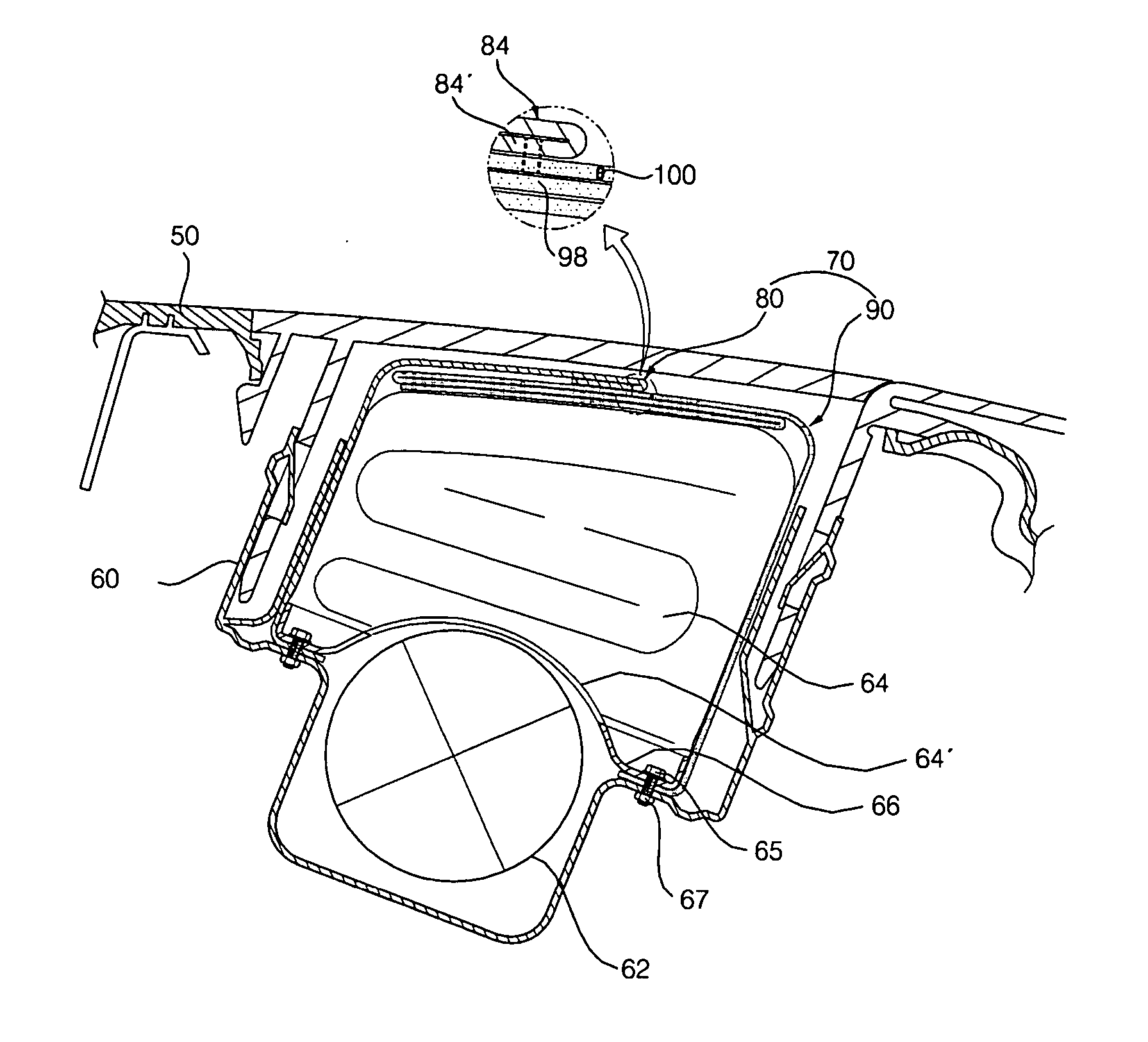
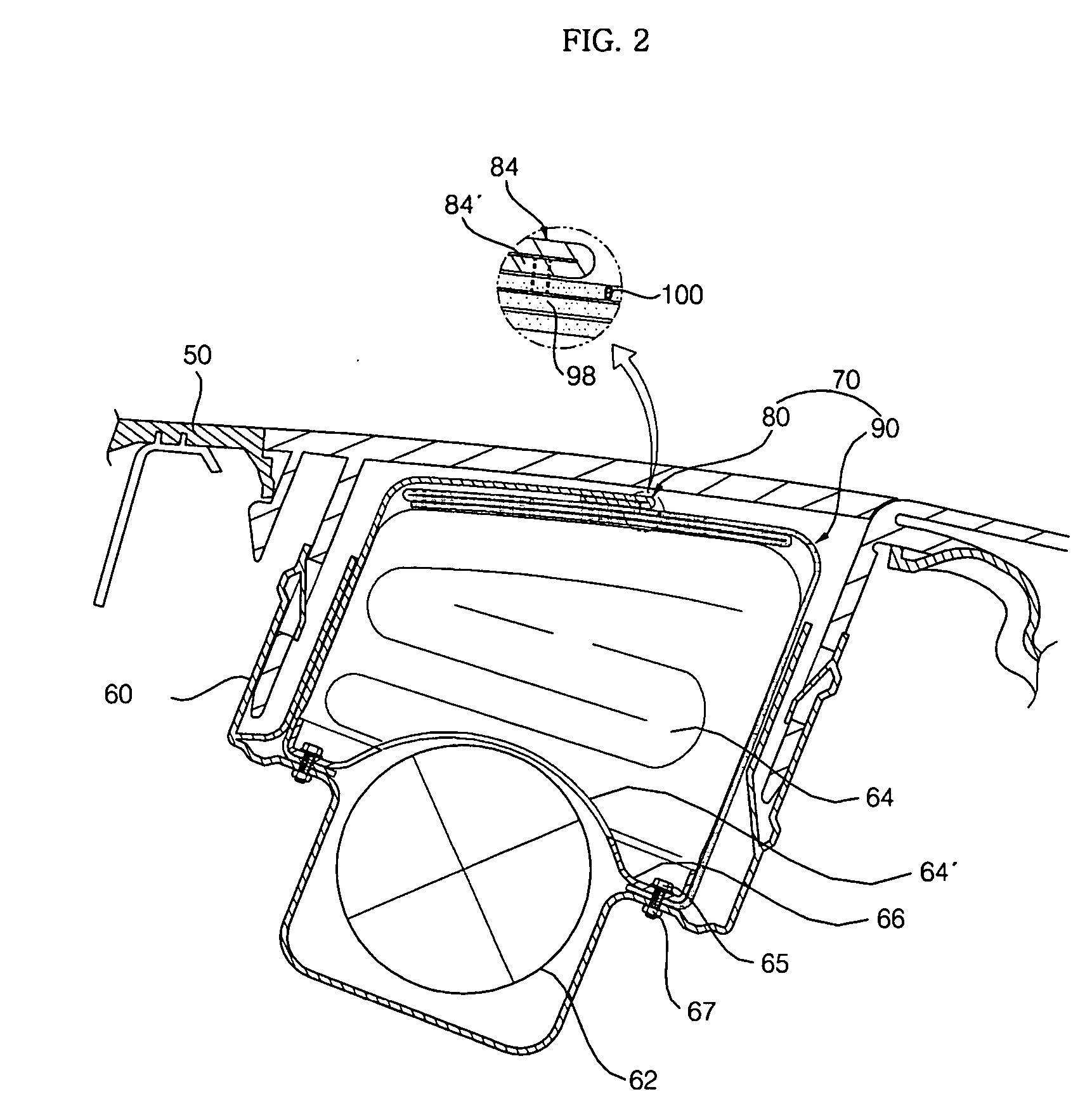
[0027]FIG. 2 is a cross sectional view of an air bag module according to the present invention. FIG. 3 is a view showing an initial deployment state of the air bag module according to the present invention. FIG. 4 is a view showing the condition after completion of deployment of the air bag module according to the present invention. FIG. 5 is a plan view showing an exploded condition of a flap unit of the air bag module according to the present invention. FIG. 6 is a deployment view showing an assembled condition of the flap unit of the air bag module according to the present invention. FIG. 7 is a deployment view of the condition during initial deployment of the flap unit of the air bag module. FIG. 8 is a deployment view showing the condition after completion of deployment of the air bag module according to the present invention.

[0028] Th...


PUM


Abstract

An air bag module includes a first flap covering one side of a cushion, and a second flap covering the other side of the cushion, the second flap having a cut-out portion that is configured to be torn gradually by an expansion pressure of the cushion and to be coupled to the first flap.

Description

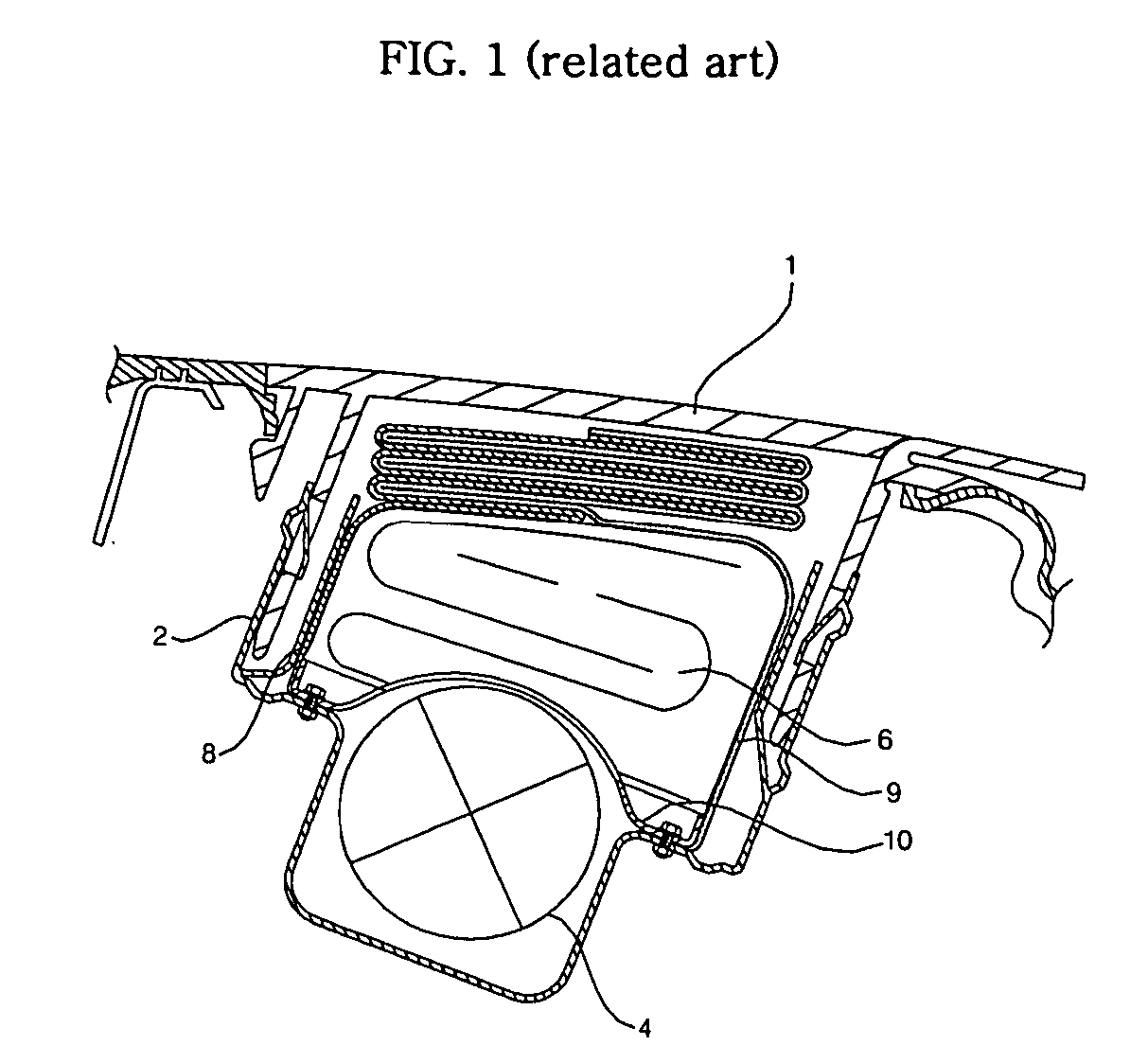
BACKGROUND OF THE INVENTION [0001] 1. Field of the Invention [0002] The present invention relates to an air bag module, and more particularly, to an air bag module which suppresses the initial deployment of a cushion by a force of gradually tearing tear lines of flaps by an expansion pressure of the cushion when an expanding gas is supplied to the cushion. [0003] 2. Description of the Background Art [0004] Generally, an air bag module is a device which is installed on a vehicle for protecting a passenger in the vehicle when a collision occurs. Such an air bag module installed on a vehicle is classified into a number of types, including a driver air bag (DAB) mounted on a handle for protecting a driver in a driver's seat, a passenger air bag (PAB) installed on an instrument panel in front of a passenger's seat for protecting the passenger in the passenger's seat, a side air bag (SAB) installed in a seat, etc. according to the installation position. [0005]FIG. 1 is a cross sectional v...

Claims


Application Information

Patent Timeline
IPC IPC(8): B60R21/217B60R21/205
CPCB60R21/205B60R21/2165B60R21/2176B60R21/2342
Inventor KWON, HAE WOOK
Owner HYUNDAI MOBIS CO LTD
Learn More