Compact oronasal patient interface

a patient interface and oronasal technology, applied in the field of patient interfaces, can solve the problems of increased treatment pressure, ineffective nasal patient interface, mouth leakage, etc., and achieve the effect of preventing or reducing mouth leakage, effective patient interface, and comfortable mouth

Active Publication Date: 2007-06-28
RESMED LTD
View PDF98 Cites 285 Cited by
  • Summary
  • Abstract
  • Description
  • Claims
  • Application Information

AI Technical Summary

Benefits of technology

[0019] In accordance with a first aspect of the invention there is provided a comfortable, effective patient interface which provides a supply of air or breathable gas to a patient's nasal passages and which prevents or reduces mouth leak.
[0021] In accordance with another aspect of the invention there is provided a patient interface that provides an effective seal with both the patient's mouth and the patient's nasal passages.
[0022] In one form the invention comprises a mouth covering chamber, a nozzle assembly and a structure to provide flexibility therebetween.
[0023] Another aspect of the invention relates to reducing contact area when compared to most known full face masks. This allows a far reduced headgear tension to be applied, significantly improving patient comfort. Patient comfort is further enhanced since the patient is less likely to feel claustrophobic, particularly with the removal of any mass that is close to the eyes.

Problems solved by technology

Comfort and effectiveness remain a continuing challenge for engineers and designers of the interface between a mechanical ventilator and a patient.
A number of patients thus find that during sleep when muscles relax, mouth leak may occur.
Alternatively some patients are naturally mouth breathers and thus find a nasal patient interface ineffective.
Mouth leak is undesirable as among other difficulties, it may result in noise, increased treatment pressure to compensate for the leak or an increased load on the nasal passages and potentially nasal obstruction or a runny nose.
Typically this is not achieved for the entire range of patients and some form of leak occurs.
The problem is heightened during sleep when the jaw moves and the head position changes.
This action can often serve to dislodge the mask and cause leak.
Since leak can be noisy and results in less-effective treatment, users often compensate by tightening the headgear more than is required.
This is detrimental for patient comfort and can cause skin breakdown.
A further problem encountered by patients who are using full face, nasal or nose and mouth masks is that the portion of the patient interface that seals around the nasal bridge prevents the patient from wearing spectacles.
Additionally it may give the sensation of being closed in, leading to a feeling of claustrophobia, particularly when combined with a mouth-sealing portion.
A further disadvantage is that any leaks that may occur can affect the sensitive area surrounding the eyes.
The device does not provide a mouth seal.
Again this does not provide any structure for sealing the mouth.
This has a ballooning seal in order to fit the patient's nose and facial contours but does not provide a mouth seal.
Whilst providing a facial contour and sealing mechanism that incorporates both the nasal and mouth, this mask cannot flex to adapt to changes in jaw movement and head position throughout the night.
The oral device is clenched between the teeth which may lead to discomfort and if mask pressures are high can lead to the slow creep of gums around the teeth due to the sustained load.
The mouth portion may prove irritating and lead to discomfort when used for long periods.
A problem with patient interfaces which incorporate oral appliances is that they can be uncomfortable for patients.

Method used


Image

  • Compact oronasal patient interface
  • Compact oronasal patient interface
  • Compact oronasal patient interface

Examples


first embodiment

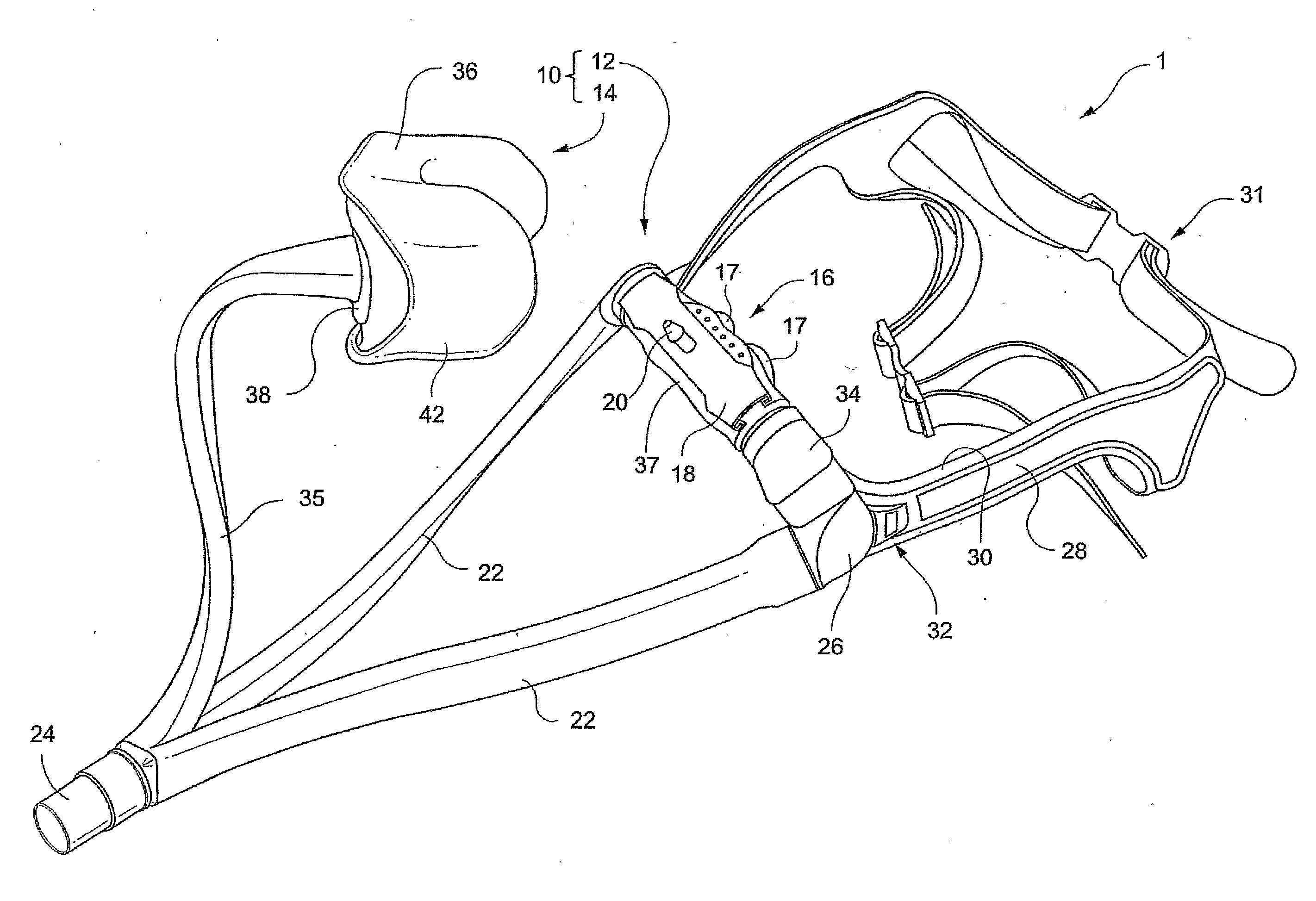
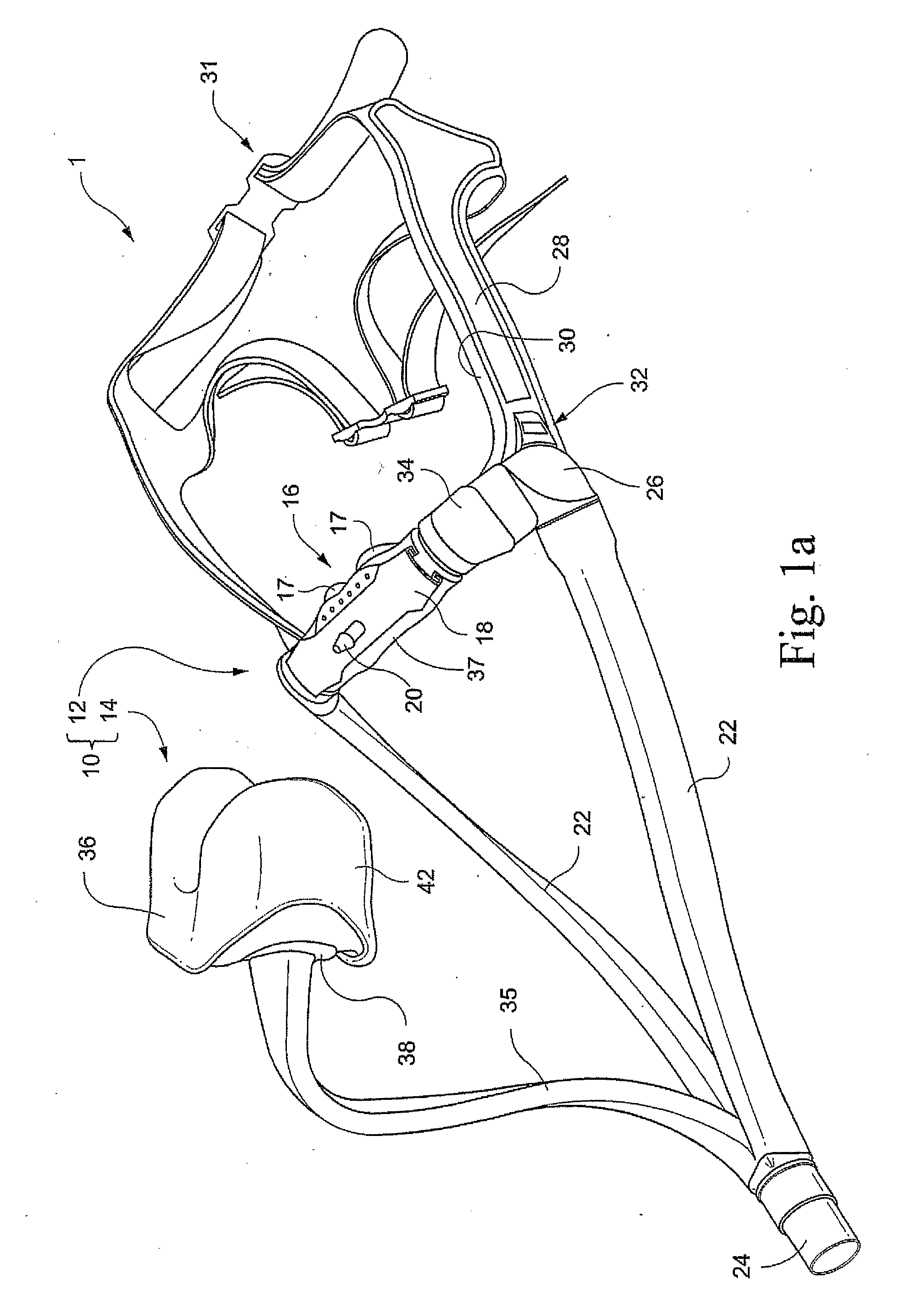
[0058]FIGS. 1a-1d illustrate the present invention. As shown in FIG. 1a, a headgear assembly 1 includes a patient interface having a dual chamber assembly 10 including an upper chamber 12 and a lower chamber 14. As shown in FIG. 1a, the lower chamber 14 is in a disconnected position, while FIGS. 1b-1d shown the upper and lower chambers in a connected position.

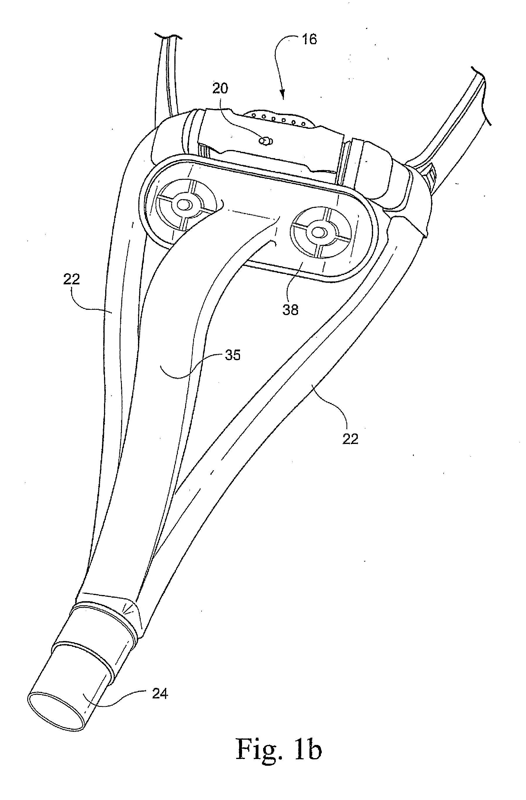
[0059] Referring to FIG. 1a, the upper chamber 12 includes a nozzle assembly 16 supported by a frame including a first connector on each lateral end thereof, as described in U.S. patent application Ser. No. 10 / 781,929, filed Feb. 20, 2004 and incorporated herein by reference in its entirety. The nozzle assembly 16 is secured to the frame via a clip 18 which in this embodiment supports a pressure measurement port 20. The nozzle assembly 16 may include a pair of nozzles 17 (see FIGS. 1c and 1d).

[0060] One or more inlet conduits 22 is supplied with breathable gas under pressure via a joint 24 coupled to an air delivery tube, whic...

second embodiment

[0066]FIGS. 2a and 2b show the invention. In this embodiment, the lower chamber 14 does not have a direct inlet conduit, like the inlet conduit 35 in FIG. 1a, but instead the air is directed to the upper chamber 12 via the inlet conduits 22 only. Air travels through the flexible element, i.e., through first and second surfaces 36 and 37, from the upper chamber 12 to the lower chamber 14, for example, thus allowing both nose and mouth breathing. FIG. 2b best showed the position where the flexible element would be located between the first and second surfaces 36, 37.

[0067]FIG. 2c shows one example of how the upper and lower chambers 12, 14 may communicate with one another. A mechanical fastener 90 includes first and second parts 92 and 94. The first part 92 may take the form of a thin plate attached to an inside surface 37a of the second part 37 formed on the upper chamber 12. The first part includes an aperture 96. The second part 94 may include a thin plate positioned on the inside ...

third embodiment

[0069] In the invention, as shown in FIGS. 3a and 3b, inlet air is directed directly to the lower chamber 14 through a swivel assembly 50. The upper chamber 12 does not have any inlet conduits but instead the air is directed to the upper chamber 12 by traveling through a conduit extending from the first surface 36 to the second surface 37. The use of a swivel assembly 50 has the advantage that the inlet conduit (not shown, but connected to end 52 of swivel assembly 50) can be routed from any direction. Further, nozzle assembly 16 need not be provided with second connectors 34 and elbow connectors 26 as shown in FIG. 1a. Instead, a pair of plugs 54 may be placed into each end of the nozzle assembly 16, as described in U.S. patent application Ser. No. 10 / 781,929, filed Feb. 20, 2004 and entitled “Nasal Assembly”, incorporated herein by reference in its entirety.


PUM


Abstract

A breathing arrangement includes a patient interface, at least one inlet conduit, and a headgear assembly. The patient interface includes a mouth covering assembly including a cushion structured to sealingly engage around exterior of a patient's mouth in use, a nozzle assembly including a pair of nozzles structured to sealingly engage within nasal passages of a patient's nose in use, and a flexible element connecting the mouth covering assembly and the nozzle assembly. The at least one inlet conduit is structured to deliver breathable gas into at least one of the mouth covering assembly and the nozzle assembly for breathing by the patient. The headgear assembly is removably connected to at least one of the mouth covering assembly and the nozzle assembly so as to maintain the mouth covering assembly and the nozzle assembly in a desired position on the patient's face.

Description

CROSS-REFERENCE TO RELATED APPLICATIONS [0001] This application claims the benefit of U.S. Provisional Application No. 60 / 533,214, filed Dec. 31, 2003, which is incorporated herein in its entirety.FIELD OF THE INVENTION [0002] The present invention relates to a patient interface for use between a patient and a structure to deliver a breathable gas to the patient, such as is used in gas delivery systems for respiratory therapy. Examples of such therapy are Continuous Positive Airway Pressure (CPAP) treatment, assisted respiration or Non-Invasive Positive Pressure Ventilation (NIPPV). BACKGROUND OF THE INVENTION [0003] Comfort and effectiveness remain a continuing challenge for engineers and designers of the interface between a mechanical ventilator and a patient. Such patient interfaces are currently employed for a variety of purposes including the delivery of non-invasive ventilation or for the delivery of pressurized air to persons who suffer from sleep disordered breathing conditi...

Claims


Application Information

Patent Timeline
Patent Type & Authority Applications(United States)
IPC IPC(8): A62B18/02A62B18/08A61M16/06
CPCA61M16/06A61M16/0666A61M16/0616A62B18/084A61M16/0611A61M16/0683A61M16/0825A61M16/0858A61M16/208A61M16/0622A61M16/0816A61M16/0057
Inventor DAVIDSON, AARONGUNARATNAM, MICHAELLYNCH, SUSANRAJE, MILINDROBINSON, GARYLUBKE, STEVENSMART, GREGORYKWOK, PHILIPSCHEINER, RUPERT
Owner RESMED LTD
Why Eureka
Try Eureka