Tool and a cutting insert for chip removing machining

a technology for removing tools and cutting inserts, which is applied in the direction of manufacturing tools, turning machine accessories, shaping cutters, etc., can solve the problems of extreme position precision requirements, catastrophic edge position precision, and unsatisfactory machining precision, so as to simplify and cheapen the manufacture

Inactive Publication Date: 2007-07-12
SANDVIK INTELLECTUAL PROPERTY AB
View PDF5 Cites 21 Cited by
  • Summary
  • Abstract
  • Description
  • Claims
  • Application Information

AI Technical Summary

Benefits of technology

[0009] Yet another object of the invention is to simplify and cheapen the manufacture of, primarily, the cutting inserts.
[0010] Still another object is to provide a tool that

Problems solved by technology

In many applications, the requirements of position precision are extreme.
This means that the active edge of the cutting insert very well may end up in the desired position, in which case the outcome of the insert production is good, but when the outcome is worse (so far that the cutting insert has swollen and become longer, or shrinked and become shorter than intended), the position of the cutting edge in relation to the basic body may deviate to such a high extent from the desired position that the machining precision will be unsatisfactory.
In this case—when the rear clearance surface of the cutting insert formed a reference point that determined the space position of the front edge—the position precision of the edge could become catastrophically poor, provided that the cutting insert was not ground, because the distance between the active edge and the opposite clearance surface is—in this connection—considerable, in particular when the tools and the cutting inserts are big.
By the fact that the central ridge is halfway between opposite sides/edges of the cutting insert, the distance is halved between the active cutting edge and the locating reference point, with the ensuing halving of the tolerance errors.
However, also this position precision has been unsatisfactory in ma

Method used


Image

  • Tool and a cutting insert for chip removing machining
  • Tool and a cutting insert for chip removing machining
  • Tool and a cutting insert for chip removing machining

Examples


Embodiment Construction

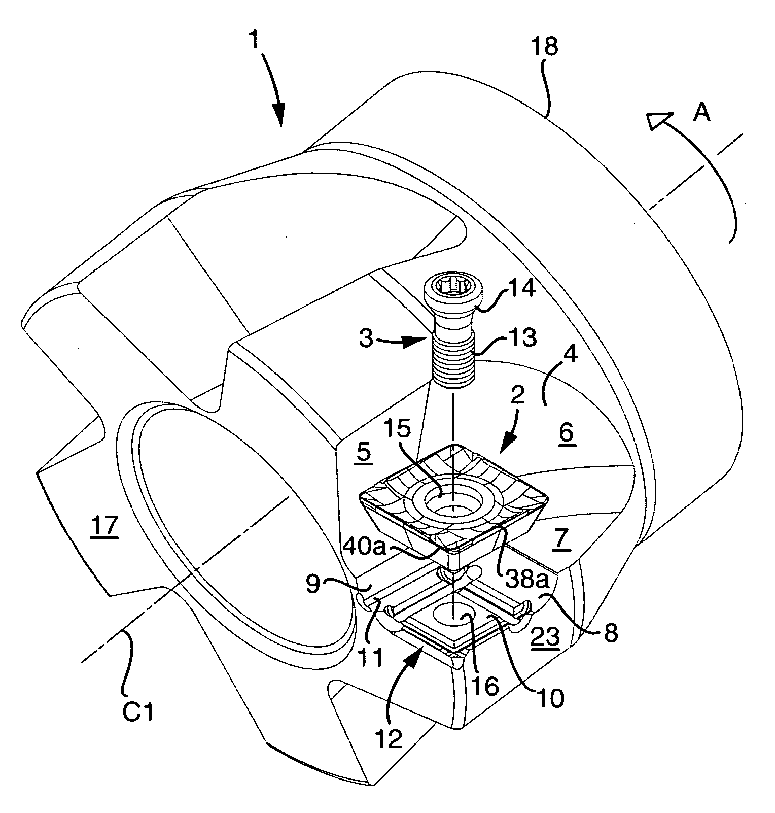
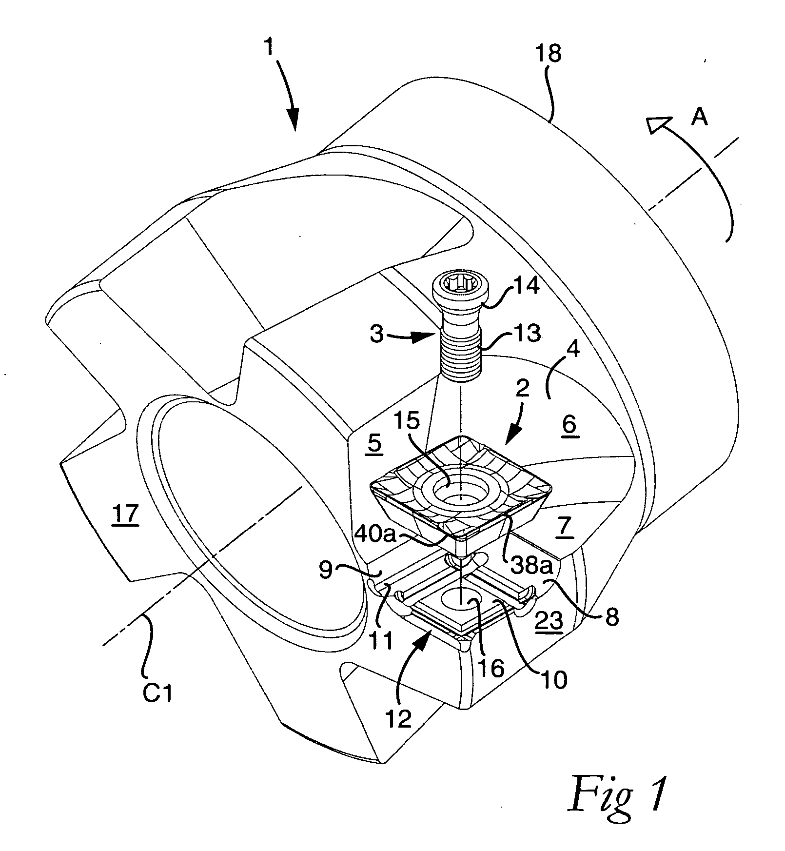
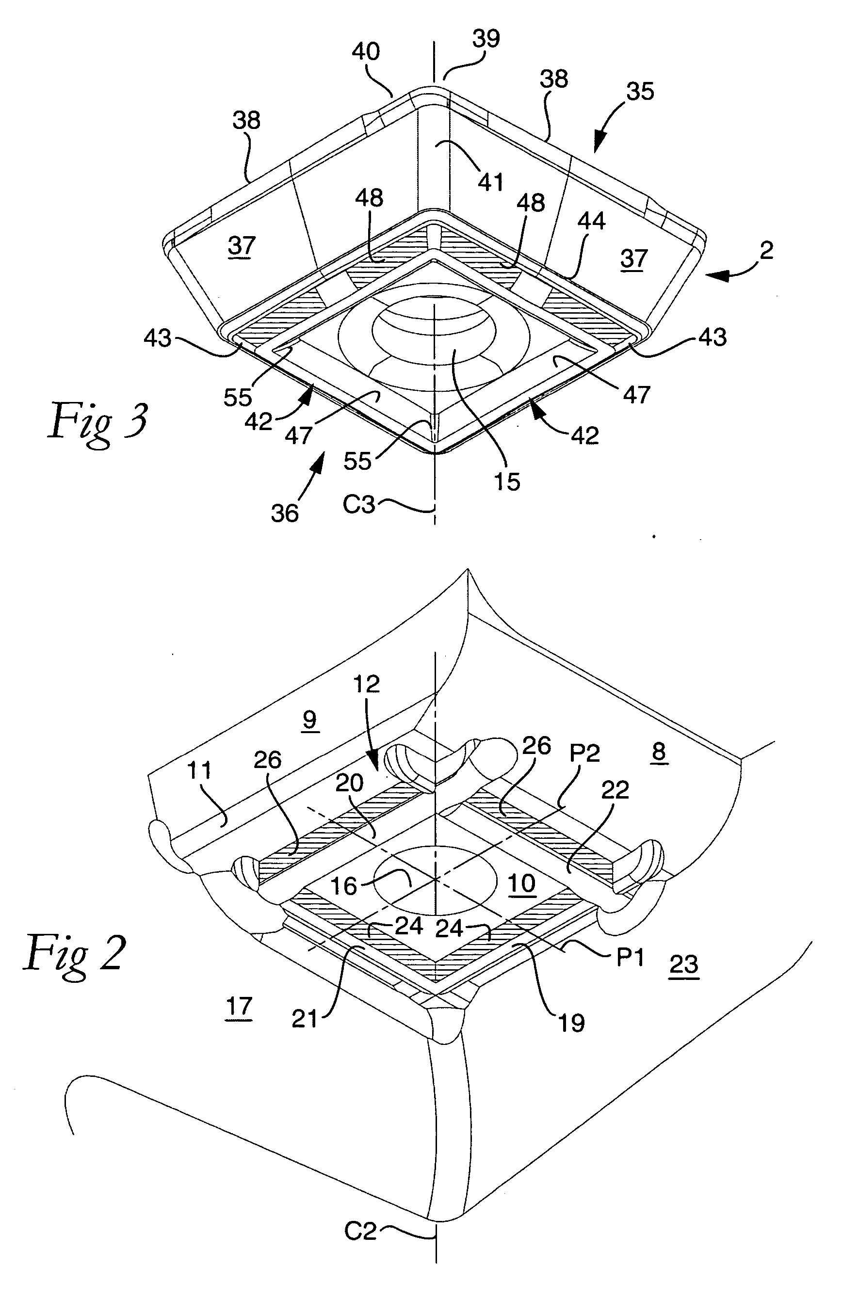
[0041] Before the invention is described closer, reference being made to the appended drawings, the implication of certain concepts, used to define the features that characterize the invention, are briefly elucidated below.

[0042]“Connecting surfaces” are two mating surfaces that form an interface between the basic body and cutting insert of the tool, one of which is included in an underside of the cutting insert, and the other one of which is formed in the basic body.

[0043]“Chip surface” is the surface that forms the topside of the cutting insert, and which in flat cutting inserts is generally parallel to the underside. The chip surface as such does not need to be planar, but has most often an irregular topography. In connection with the invention, the chip surface is incidental.

[0044]“Clearance surface” is the surface that extends between the topside and the underside of the cutting insert. When the cutting insert has a positive geometry, the clearance surface forms an acute ang...


PUM

PropertyMeasurementUnit
Fractionaaaaaaaaaa
Angleaaaaaaaaaa
Thicknessaaaaaaaaaa

Abstract

A tool and a cutting insert for chip removing machining, such as milling, turning or the like. The cutting insert includes a chip-removing main edge, which is separated from a center of the cutting insert and from which a clearance surface extends toward a transition to an underside in the form of a connecting surface, in which an elongate engagement means, e.g., a ridge, is included, which is situated nearer the transition than the center of the cutting insert, and includes a flank having the purpose of transferring cutting forces in the direction transverse to the length extension of the ridge. The ridge is the only active engagement means of an imaginary triangle between the center of the cutting insert and opposite ends of the transition, besides which the flank has a cross section-wise convex shape. In such a way, the active edge of the cutting insert is located in a desired exact position in relation to the tool, even if the cutting insert is impaired by minor form defects.

Description

[0001] This application claims priority under 35 U.S.C. § 119 to Sweden Patent Application No. 0502712-3, filed on Dec. 8, 2005, the disclosure of which is incorporated by reference herein in its entirety. FIELD OF THE INVENTION [0002] The present invention relates generally to a tool for chip removing machining of the type that includes a basic body having an insert seat that is defined by a center and is in the form of a connecting surface, in which there is included an elongate and female- or male-like, primary engagement means spaced apart from the center, and a replaceable cutting insert having at least one chip-removing main edge, which is spaced apart from a center of the cutting insert, and from which a clearance surface extends toward a transition to an underside in the form of a connecting surface, in which an elongate and male or female-like, secondary engagement means is included, which is positioned nearer the transition than the center of the cutting insert, and includ...

Claims


Application Information

Patent Timeline
IPC IPC(8): B23P15/28
CPCB23C5/2213B23C2200/161Y10T407/24Y10T407/23Y10T407/2202B23C2200/165B23B27/1607B23C5/2239B23C5/2298B23B27/16
Inventor PANTZAR, GORAN
Owner SANDVIK INTELLECTUAL PROPERTY AB
Why Eureka
Try Eureka