Data synchronization across an asynchronous boundary using, for example, multi-phase clocks

a data synchronization and asynchronous boundary technology, applied in digital transmission, pulse automatic control, instruments, etc., can solve problems such as inability to design associated circuits, metastable latch problems, and invalid logi

Active Publication Date: 2007-06-12
UNIVERSAL CONNECTIVITY TECH INC
View PDF8 Cites 13 Cited by
  • Summary
  • Abstract
  • Description
  • Claims
  • Application Information

AI Technical Summary

Benefits of technology

[0018]If the system determines that the phase difference between the edges of the clock signals is less than a pre-selected value, the method samples the incoming data with a second internal sampling clock signal, having a selected phase relationship to the first internal sampling clock signal. For example, if the system determines that the rising edge of the external clock signal is near to that of a first internal clock signal, then the system effectively latches data based on a falling edge of the external clock signal (based on a second clock signal 180° out of phase with the first internal clock signal). By maintaining sufficient phase difference between the active edge of the external clock and the active edge of the internal sampling clock, the system provides a sufficient setup / hold margin to avoid a metastability or other problem in the subsystem receiving data across an asynchronous boundary.
[0019]By obtaining information about the phase of the external clock, an embodiment according to the invention can avoid this metastability problem. This embodiment uses two phases of multi-phase clock signals to obtain information about the phase of an external clock, and thereby determine whether a first 0th clock signal, or a 180° out of phase second phase clock signal is to be used.

Problems solved by technology

Without such resynchronization, a hardware “metastability” problem can result in clocked devices of the receiving subsystem, thereby producing invalid logic results.
With insufficient overlap, such as setup time violation or hold time violation can occur when a clock pulse is poorly synchronized with a data pulse, the bistable latch output can move from one stable level to the other and then back again.
In the context of two distinct clock domains, the metastable latch problem occurs when a clock pulse from one domain overlaps insufficiently with a data pulse synchronized to a clock pulse from another domain.
However, if the input changes at a particularly bad time within the setup-time, the clocked bistable latch can hover at the logic threshold or the clocked bistable latch can go into one state and then switch back to the other state.
However, a higher frequency clock requires circuitry to have less margin of error, thereby making associated circuitry more difficult to design.

Method used


Image

  • Data synchronization across an asynchronous boundary using, for example, multi-phase clocks
  • Data synchronization across an asynchronous boundary using, for example, multi-phase clocks
  • Data synchronization across an asynchronous boundary using, for example, multi-phase clocks

Examples


Embodiment Construction

[0016]The invention will now be described with respect to various embodiments. The following description provides specific details for a thorough understanding of, and enabling description for, these embodiments of the invention. However, one skilled in the art will understand that the invention may be practiced without these details. In other instances, well known structures and functions have not been shown or described in detail to avoid unnecessarily obscuring the description of the embodiments of the invention. For each embodiment, the same reference numbers and acronyms identify elements or acts with the same or similar functionality for ease of understanding and convenience.

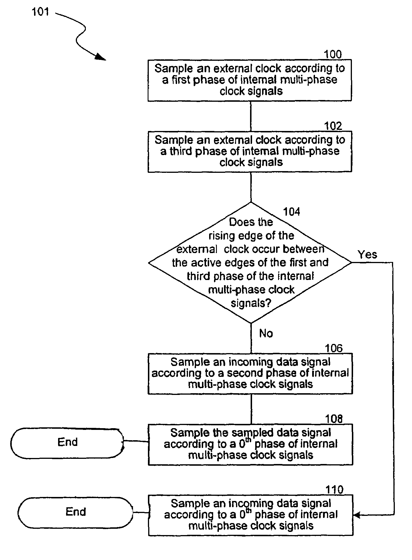
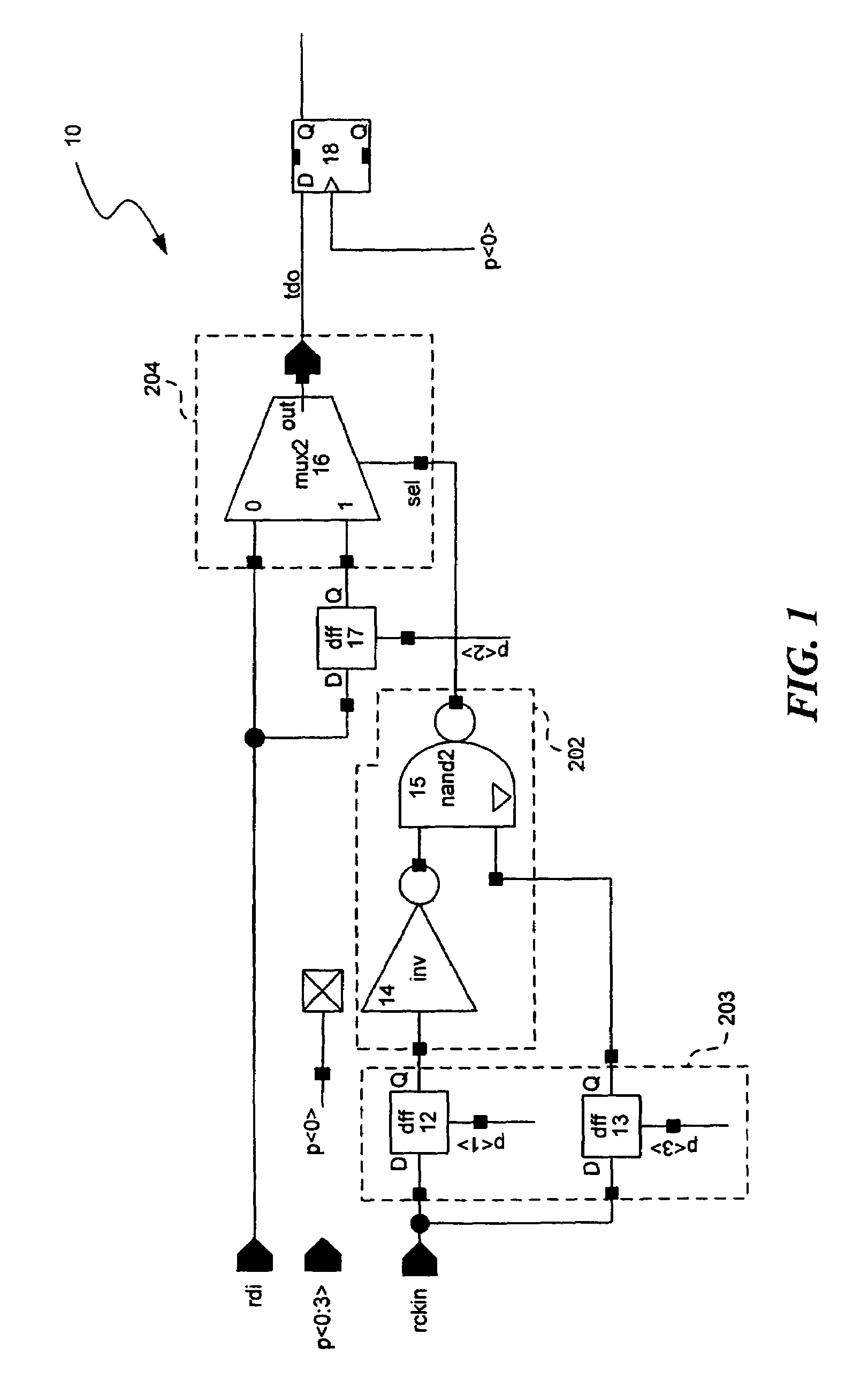
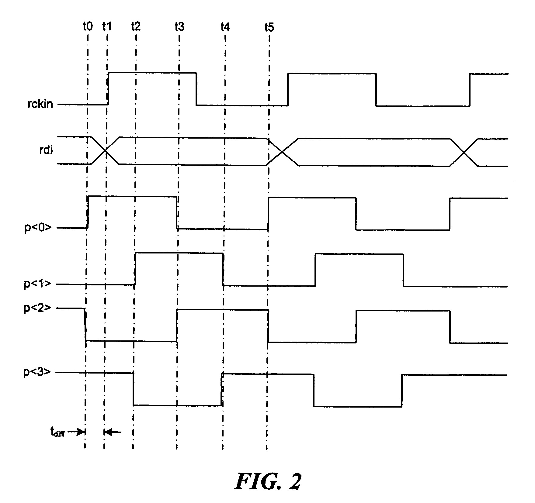
[0017]This invention relates to systems and methods for transferring synchronous digital signals, such as across an asynchronous boundary. Data transfer over a boundary separating an external clock domain and an internal clock domain can cause elements of the receiving circuit to enter a metastable state. ...


PUM


Abstract

Additional information on the phase of an external clock signal is obtained by using clock signals to determine if a phase difference between an external clock signal and a first internal sampling clock signal is less than a pre-selected value. If the system determines that the phase difference is less than a pre-selected value, one embodiment samples the incoming data with a second internal sampling clock signal, having a selected phase relationship to the first internal sampling clock signal, such as ½ a clock period out of phase. By maintaining sufficient phase difference between the active edge of the external clock and the active edge of the internal sampling clock, the embodiment provides a sufficient setup / hold margin to avoid a metastability or other problem in a subsystem receiving data across an asynchronous boundary.

Description

BACKGROUND[0001]1. Technical Field[0002]Embodiments of the invention relate to systems and methods for transferring synchronous digital signals across an asynchronous boundary.[0003]2. Description of the Background[0004]In systems using digital circuitry, two functional blocks or subsystems operating in two different timing domains often communicate with one another. When these two blocks operate in synchrony with a single digital clock signal, transfer of digital data between the two blocks does not present a problem. However, when two digital subsystems operate in synchrony with different clock signals, any digital data signals traveling between the subsystems should be synchronized in some manner to avoid data errors.[0005]If, for example, two digital subsystems operate in synchrony with different clocks, the system should resynchronize the digital data signals traveling from one subsystem to the other subsystem. In other words, if data signals travel from a first subsystem in an...

Claims


Application Information

Patent Timeline
Patent Type & Authority Patents(United States)
IPC IPC(8): H04L7/00
CPCH04L7/0008H04L7/0012
Inventor KIM, GYUDONGKIM, MIN-KYU
Owner UNIVERSAL CONNECTIVITY TECH INC
Why Eureka
Try Eureka