Motor protector endshield mounting bracket

Inactive Publication Date: 2007-08-23
NIDEC MOTOR CORP
View PDF6 Cites 7 Cited by
  • Summary
  • Abstract
  • Description
  • Claims
  • Application Information

AI Technical Summary

Benefits of technology

[0005] In one aspect, a bracket for mounting a motor protector on an endshield of a motor comprises a tube sized and shaped for receiving the protector. The tube includes at least one integrally fo

Problems solved by technology

However, in order to meet UL limited short circuit testing and electrical spacing requirements, additional devices are often needed.
However, this bracket is not appropriate for manual reset protectors because it is not designed to handle the load imposed by pushing the manual reset button.
It also

Method used


Image

  • Motor protector endshield mounting bracket
  • Motor protector endshield mounting bracket
  • Motor protector endshield mounting bracket

Examples


Example

[0014] Corresponding reference characters indicate corresponding parts throughout the drawings.

DETAILED DESCRIPTION OF THE DRAWINGS

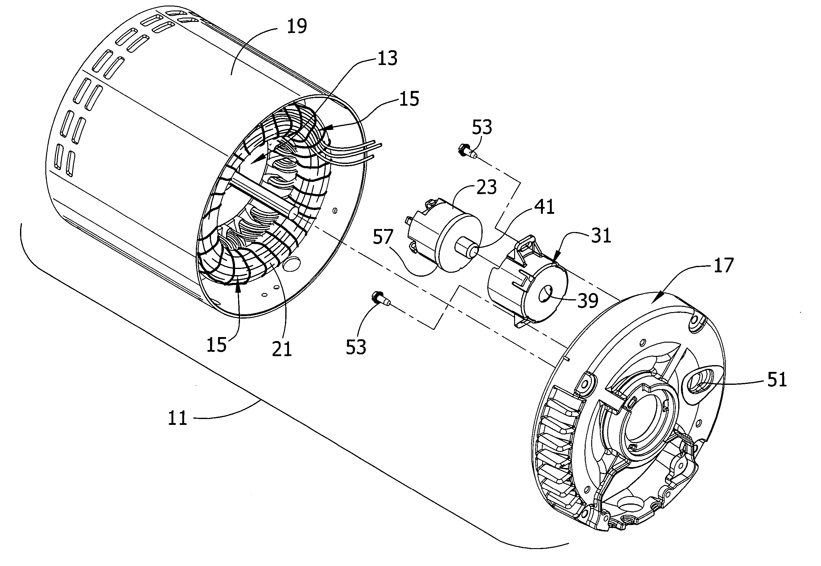
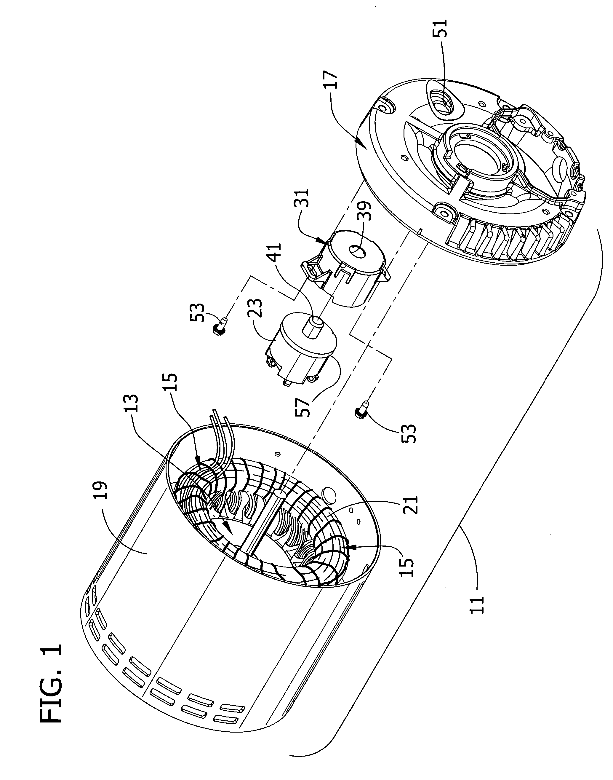
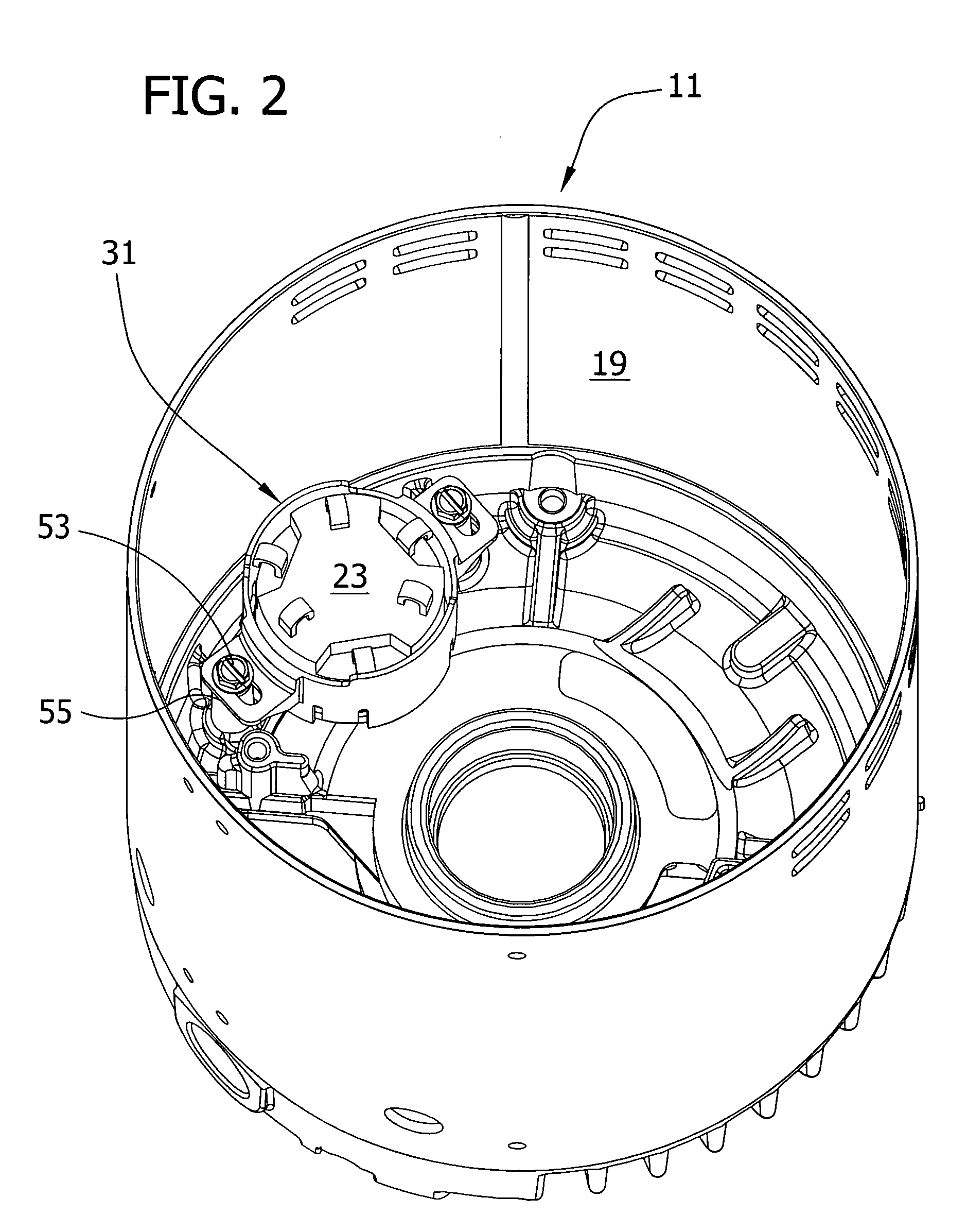
[0015] Referring to FIG. 1, an electric motor 11 of one embodiment generally comprises a rotor 13, a stator 15 in magnetic coupling relation to the rotor, an endshield 17, and a housing 19 receiving the rotor and stator. The stator 15 generally includes windings 21 that are connected to a manual reset motor protector 23. The protector 23 may also be connected to other components, such as a power connection (terminal) board (not shown). The endshield 17 is disposed at one end of the rotor 13 and stator 15. This general motor configuration is merely one example, and many other configurations are contemplated within the scope of this invention. A bracket 31 is generally adapted to receive the protector and secure it between the endshield 17 and stator 15.

[0016] Referring now to FIGS. 3 and 4, the bracket 31 of this embodiment comprises a tube 33 having a...


PUM


Abstract

A bracket for mounting a motor protector on an endshield of a motor comprises a tube sized and shaped for receiving the protector. The tube includes at least one integrally formed fastener for fastening the protector to the bracket. At least one integrally formed projection extends outwardly from the tube to facilitate fastening the bracket to the endshield of the motor.

Description

FIELD OF THE INVENTION [0001] The present invention relates generally to a motor having a bracket for mounting an electric motor protector, and more particularly to a bracket for mounting a motor protector to an endshield of the motor. BACKGROUND OF THE INVENTION [0002] Manual reset motor protectors are used to cut power to a motor under conditions that may damage the motor, such as overheating or electrical overload. Once the source of the problem has been corrected, the power to the motor is restored by pushing a reset button located on the protector. Such protectors should be mounted as close to the windings of the motor as possible so that they can detect the heat of the windings. However, the manual reset button on the protector should be accessible from outside the motor. Accordingly, it is often desirable to mount the protector to the inside of the motor endshield. [0003] Many manual reset motor protectors include mounting “ears” that allow the protector to be mounted to an e...

Claims


Application Information

Patent Timeline
IPC IPC(8): H02K11/00H02K5/00
CPCH02K5/04H02K11/0057H02K11/0047H02K11/25H02K11/27
Inventor JONES, PATRICK M.
Owner NIDEC MOTOR CORP
Why Eureka
Try Eureka