Baffle plate for oil pan

Active Publication Date: 2019-05-23
HONDA MOTOR CO LTD
View PDF0 Cites 0 Cited by
  • Summary
  • Abstract
  • Description
  • Claims
  • Application Information

AI Technical Summary

Benefits of technology

[0026]Thereby, the fastening of the baffle plate to the cylinder block is facilitated, and the stiffness of the baffle plate can be enhanced.
[0027]The present invention t

Problems solved by technology

However, the arrangement proposed by JP4016932B has the drawback that

Method used


Image

  • Baffle plate for oil pan
  • Baffle plate for oil pan
  • Baffle plate for oil pan

Examples


Example

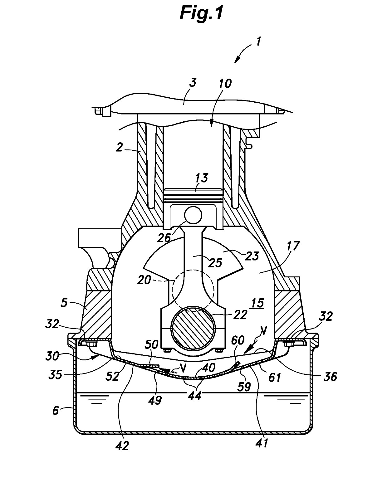
[0032]A baffle plate for an oil pan of an internal combustion engine according to a first embodiment of the present invention is described in the following with reference to FIGS. 1 to 3. In the following description, the terms “downstream” and “upstream” are used in regard to the air flow created by the rotation of the crankshaft, and this also corresponds to the direction of the movement of the lower part of the crankshaft.

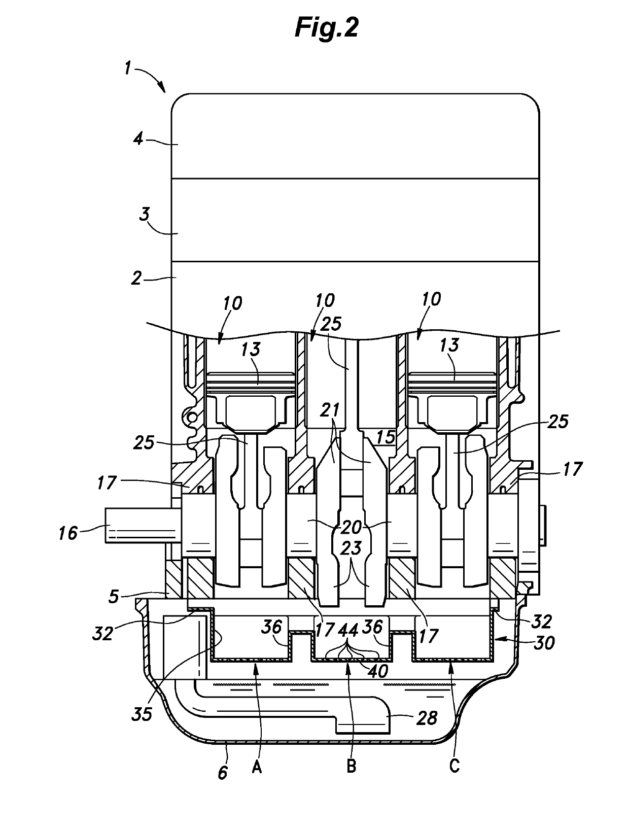
[0033]As shown in FIGS. 1 and 2, the internal combustion engine 1 consists of an in-line three cylinder reciprocating engine, and includes an upper block 2, a cylinder head 3 connected to the upper end of the upper block 2, a head cover 4 connected to the upper end of the cylinder head 3, a lower block 5 connected to the lower end of the upper block 2, and an oil pan 6 connected to the lower end of the lower block 5. The upper block 2 and the lower block 5 jointly form a cylinder block.

[0034]As shown in FIG. 2, three cylinders 10 are defined in the cylinder bloc...


PUM


Abstract

A baffle plate includes a curved part which in turn includes a bottom portion (40), an upstream inclined portion (41), and a downstream inclined portion (42). A part of the downstream inclined portion adjacent to the bottom portion is provided with a first downstream through hole (49) elongated in the axial direction of the crankshaft, and a downstream side wall (50) extending from a downstream edge of the first downstream through hole in an upstream direction with respect to the rotational direction of the crankshaft, and a part of the downstream inclined portion remote from the bottom portion is provided with a plurality of second downstream through holes (52).

Description

[0001]TECHNICAL FIELD[0002]The present invention relates to a baffle plate provided in an upper part of an oil pan of an internal combustion engine.BACKGROUND ART[0003]In a conventional wet sump internal combustion engine, a baffle plate is provided in an upper part of an oil pan, and a bottom portion of the baffle plate is provided with a laterally elongated through hole. A slat extends from a downstream edge of the through hole toward the upstream side. See JP3552414B. This baffle plate allows the lubricating oil that is deposited on the upper surface of the baffle plate to be expelled to the oil reservoir in the oil pan via the through hole of the baffle plate by using the air flow created by the rotation of the crankshaft. However, this air flow impinges directly upon the surface of the oil in the oil reservoir via the through hole so that the oil may be aerated.[0004]JP4016932B proposes to provide a through hole in a part of the baffle plate offset from the center thereof with ...

Claims


Application Information

Patent Timeline
IPC IPC(8): F01M11/00F02B75/20
CPCF01M11/0004F02B75/20F01M2011/0033F01M2011/005
Inventor ONO, TAKUYASUENAGA, ATSUSHIYODA, OSAMUASAME, KOICHIRO
Owner HONDA MOTOR CO LTD
Why Eureka
Try Eureka