Wheel bearing assembly comprising a joint and corresponding method of manufacture

Inactive Publication Date: 2013-06-13
AB SKF
View PDF14 Cites 4 Cited by
  • Summary
  • Abstract
  • Description
  • Claims
  • Application Information

AI Technical Summary

Benefits of technology

[0031]In one embodiment, the step of providing face splines is performed prior to the step of pressing, which step further comprises radially deforming a trailing edge of the insert ring such that a first portion thereof extends between adjacent splines of the separate inner ring and second portion extends between adjacent splines of the flanged hub. As a result, the joint is rotationally locked with respect to the flanged hub and the sepa

Problems solved by technology

A disadvantage of welding, however, is that the resulting heat affected zone adversely affects the hardness of bearing s

Method used


Image

  • Wheel bearing assembly comprising a joint and corresponding method of manufacture
  • Wheel bearing assembly comprising a joint and corresponding method of manufacture
  • Wheel bearing assembly comprising a joint and corresponding method of manufacture

Examples


Example

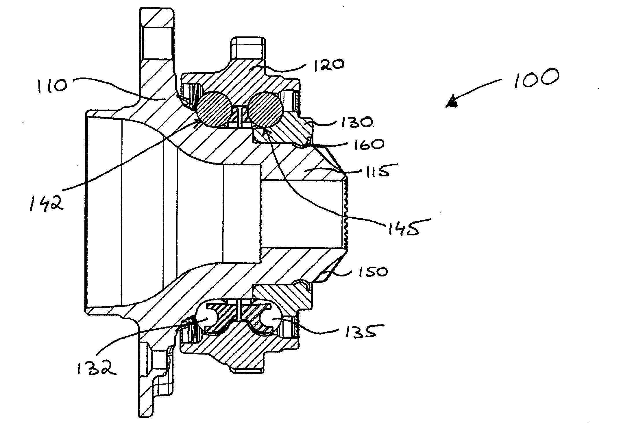
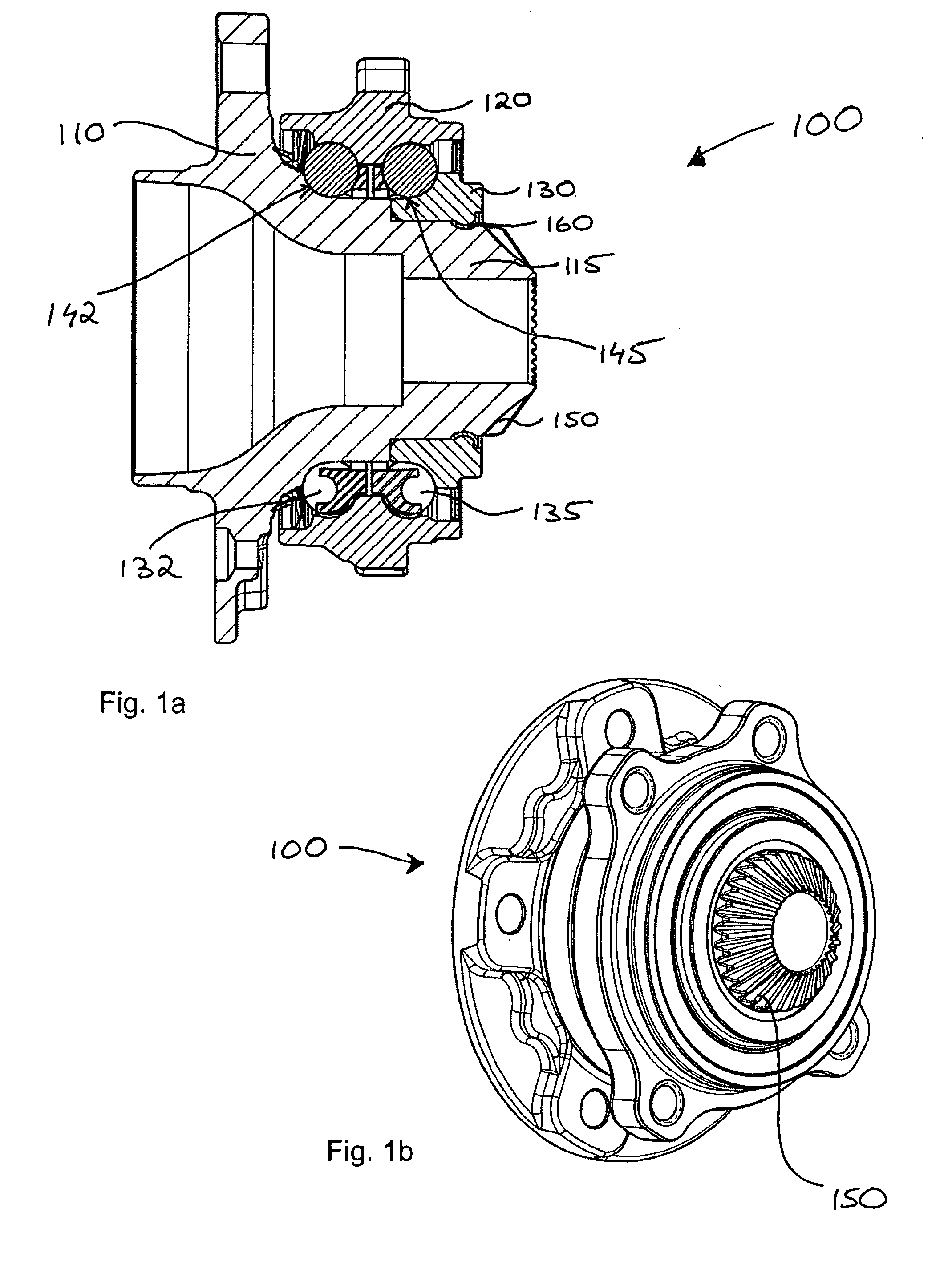
[0041]In the interests of fuel economy, there is an increasing drive towards reducing the weight of automotive components. This also applies to the components of a vehicle wheel end. Further, the vehicle wheel end is part of the unsprung mass, and reducing the unsprung mass is beneficial in terms of reducing wheel vibration. In driven applications, the weight of the wheel end is predominantly governed by the wheel bearing unit and the constant velocity joint (CVJ) which drives a flanged hub of the bearing unit. Generally, a bore of the flanged hub is provided with axially oriented splines, which engage with corresponding splines on a driveshaft of the CVJ. It has been found that a lighter weight construction is achieved by providing an inboard side face of the flanged hub with radially oriented face splines, for engagement with corresponding face splines on the CVJ. Face splines have the further advantage of being play-free and the corresponding machining process is more economical....


PUM

PropertyMeasurementUnit
Timeaaaaaaaaaa
Yield strengthaaaaaaaaaa
Thicknessaaaaaaaaaa

Abstract

The present invention resides in a wheel bearing assembly (100) comprising a flanged hub (110) and at least one second component (130) that is joined to the flanged hub by means of a radially intermediate joint (160). Specifically, the flanged hub has a first joining surface and the second component has a second joining surface, radially opposite from the first joining surface and spaced therefrom, such that a groove is defined between the first and second joining surfaces. According to the invention, the radially intermediate joint (160) is formed by an insert ring made from a high strength material that is pressed into the groove. The invention also relates to a corresponding method of manufacturing a wheel bearing unit.

Description

FIELD OF THE INVENTION[0001]The present invention relates to a wheel bearing assembly having a flanged hub that is connected to at least one other component of the assembly by means of a joint. The invention further relates to a method of manufacturing a wheel bearing assembly.BACKGROUND[0002]One example of a wheel bearing assembly comprising a joint is known from DE 102006033116. The joint in this example is a weld, which is employed to join a separate inner ring to the flanged hub such that the inner ring presses against an inboard row of rolling elements, to provide bearing preload. In many wheel bearing assemblies, such as disclosed in WO 2007014553, bearing preload is set by orbitally deforming an elongation of the flanged hub to form a collar. This collar then presses the separate inner ring against the inboard row of rolling elements. The welded joint disclosed in DE 102006033116 therefore enables a more compact bearing assembly in comparison with the assembly disclosed in WO...

Claims


Application Information

Patent Timeline
IPC IPC(8): B60B27/00B21K1/00B21D39/06
CPCB21D39/06Y10T29/49863B23P11/00F16D1/06F16D1/072F16C19/186F16C2326/02F16C43/04F16C33/60F16B17/002B21K1/00B60B27/0078F16C35/067Y10T29/49643Y10T403/7051B21K25/00F16B17/00
Inventor VAN DE SANDEN, JOHNVISSERS, CORNELIUS PETRUS ANTONIUSHAANS, VICTORKNOPF, ANDREASRE, PAOLO A.
Owner AB SKF
Why Eureka
Try Eureka