Torque limiting device

Active Publication Date: 2012-01-26
NIPPON YUSOKI
View PDF5 Cites 5 Cited by
  • Summary
  • Abstract
  • Description
  • Claims
  • Application Information

AI Technical Summary

Benefits of technology

[0050]According to the torque limiting device as per the present invention, the clutch disc clamp plate is fastened to the flywheel, and a concave space of an annular shape is formed between the clutch disc clamp plate and the flywheel. Inside of the annular concave space, the clutch disc is housed. Thus, the stiffness of the clutch disc clamp plate in the clutch pressing direction can be enhanced.
[0051]In this way, the flywheel and the clutch disc clamp plate can press the clutch disc with enhanced forces (pressures). The whole area of the friction facing can evenly come in contact with the clutch disc clamp p

Problems solved by technology

Thus, the length in the axial direction becomes great, and the clutch

Method used


Image

  • Torque limiting device
  • Torque limiting device
  • Torque limiting device

Examples


Example

First Embodiment

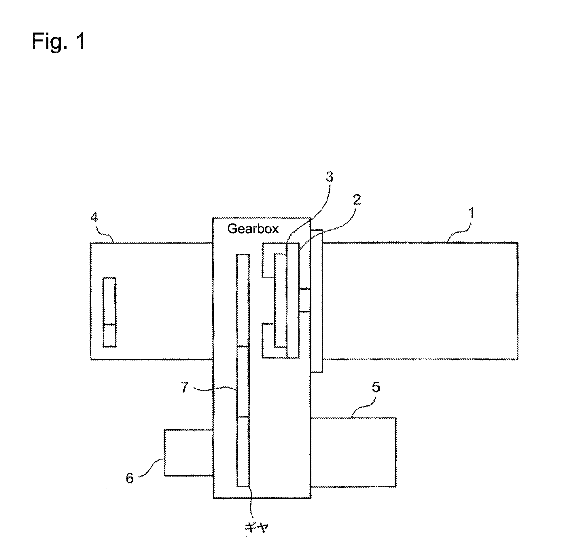
[0064]FIG. 1 shows an outline of an example of the power line (the power transmission line as a whole system) in which the device according to the present invention is integrated; in FIG. 1, the whole system includes, but not limited to: an engine 1; a flywheel 2 that is a power output part of the engine; a torque limiting device 3 according to the present invention, the device 3 being integrated inside of the flywheel (or by the side of), the device 3 limiting the to-be-transferred torque to less than an allowable level; a transmission 4; a speed reduction mechanism 7 that is provided with gears, the output shaft of the torque limiting device 3 being connected to the input shaft of the transmission 4, via the gears of the speed reduction mechanism 7. Further, the gears of the speed reduction mechanism 7 are connected to, for instance, a driving device for a forklift.

[0065]In addition, the whole system includes, but not limited to: a motor (a motor-generator) 5 that ...

Example

Second Embodiment

[0097]Based on FIGS. 5(A), 5(B) and 5(C), the torque limiting device according to a second mode of the present invention is now explained.

[0098]In this second mode, the wall face of the clutch disc clamp plate 19, the face which faces the side surface of the friction facing 24 provided at the outer regions of the clutch disc 18, is tapered so that the distance between the friction facing and the wall face becomes shorter as the radius (the distance from the rotation axis) of the position on the wall face becomes small; hereby, the distance between the friction facing and the wall face is a distance in a pressing force free condition.

[0099]The reason for the above-described contrivance is that the deformation of the clutch disc clamp plate 19 is estimated in advance; namely, since the clutch disc clamp plate 19 has an opening 16 in the central part thereof, the area in the neighborhood of the opening is inclined to deform in the rotation axis direction in comparison ...


PUM


Abstract

Providing a torque limiting device by which a high torque limitation can be set without spoiling the superior stability and wear-resistance. A torque limiting device, including, but not limited to: a clutch disc clamp plate 17 that has a surface area 13 where the surface and the outer area surface of the flywheel press or come in contact with each other, and is provided with an opening 16 at the center middle part of the clutch disc clamp plate 17 so that a concave space 14 is formed between the clutch disc clamp plate 17 and the fly wheel 2 when the clutch disc clamp plate 17 is fastened to the fly wheel 2; a clutch disc 18 that is fitted in the concave space, and connected to the driven apparatus; a clutch pressing plate 22 that is fitted between the clutch disc 18 and the fly wheel 2; and, at least one pressing means that is fitted to and in the flywheel 2 and presses the clutch pressing plate 22 in a surface contact condition.

Description

BACKGROUND OF THE INVENTION[0001]1. Field of the Invention[0002]The present invention relates to a torque limiting device that prevents a power supplying engine and a driven device driven by the engine from being loaded with the torque exceeding a predetermined limit not allowable for the engine and the driven device, when the torque (including torque fluctuations) is transferred from the power source engine to the driven device as well as from the driven engine to the power source engine.[0003]2. Background of the Invention[0004]In general, when mechanical power is transferred from an engine as a power source to a driven device, the system configured with the engine and the driven device is sometimes provided with a torque limiting device in order that the driven device is not damaged by an excessive torque that exceeds a predetermined level, the torque limiting device preventing the driven device.[0005]In the torque limiting device, for instance, the friction facings of the outer ...

Claims


Application Information

Patent Timeline
IPC IPC(8): F16D7/02F16D43/21
CPCF16D43/215F16D7/025
Inventor YAMADA, KOICHITAKETANI, YOSHINORI
Owner NIPPON YUSOKI
Why Eureka
Try Eureka