Cowl cross bar for vehicle

Active Publication Date: 2017-12-07
HYUNDAI MOTOR CO LTD +1
View PDF0 Cites 1 Cited by
  • Summary
  • Abstract
  • Description
  • Claims
  • Application Information

AI Technical Summary

Benefits of technology

[0008]Various aspects of the present invention are directed to providing a cowl cross bar for a vehicle which is configured such that the optimal coupling structure between a main cross bar in front of a driver's sea

Problems solved by technology

However, the conventional cowl cross bar is problematic in that the stiffness thereof is reduced because of the eccentri

Method used


Image

  • Cowl cross bar for vehicle
  • Cowl cross bar for vehicle
  • Cowl cross bar for vehicle

Examples


Example

First Embodiment

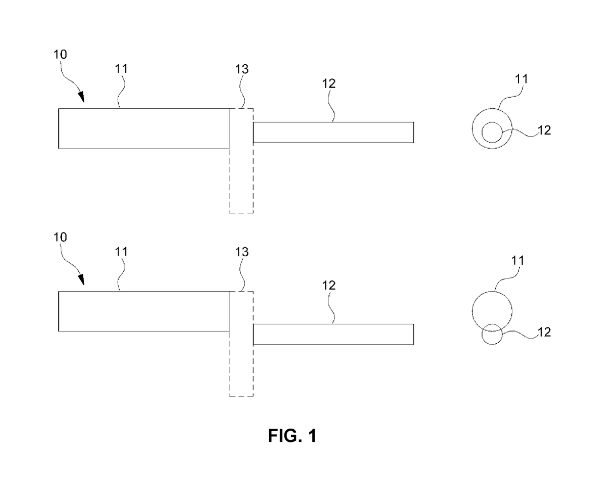
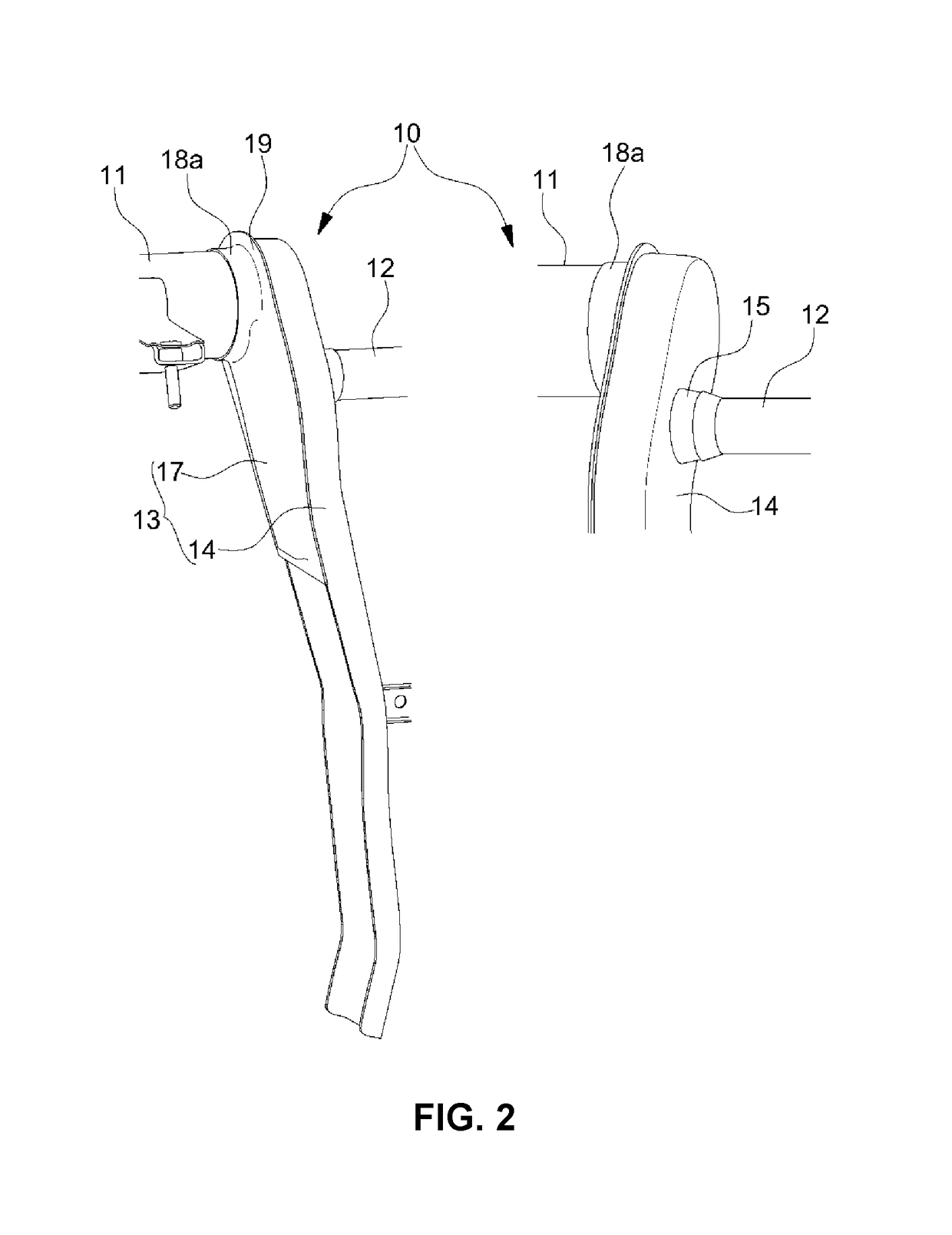
[0045]In FIG. 1, there is illustrated a schematic layout structure of a cowl cross bar provided with a center supporter according to a first embodiment. In FIGS. 2 and 3, there is illustrated a detailed structure of the center supporter according to the first embodiment.

[0046]As shown in FIG. 1, in the cowl cross bar 10, a main cross bar 11 and a sub-cross bar 12 may be disposed such that the sum of the radius of the main cross bar 11 and the radius of the sub-cross bar 12 is less than the distance between a diametric center (that is, a circle center) of the main cross bar 11 and a diametric center of the sub-cross bar 12.

[0047]As such, the cowl cross bar 10 having the layout structure of the main cross bar 11 and the sub-cross bar 12 that are disposed such that the diametric centers thereof are positioned eccentrically relative to each other includes a center supporter 13, which has a structure shown in FIGS. 2 and 3 and is provided between the main cross bar 11 and...

Example

Second Embodiment

[0058]In FIG. 4, there is illustrated a schematic layout structure of a cowl cross bar provided with a center support bracket (center supporter) according to a second embodiment. In FIGS. 5A to 8, there are illustrated a detailed structure of the center support bracket and a coupling structure between a main cross bar and a sub-cross bar, according to the second embodiment.

[0059]Typically, the main cross bar has a diameter greater than that of the sub-cross bar. Therefore, as shown in FIG. 4, in the cowl cross bar 20, the main cross bar 21 and the sub-cross bar 22 may be disposed such that the distance between a diametric center of the main cross bar 21 and a diametric center of the sub-cross bar 22 is a value obtained by subtracting the radius of the sub-cross bar 22 from the radius of the main cross bar 21. For reference, the length of the sub-cross bar 22 is greater than that of the main cross bar 21.

[0060]As such, the cowl cross bar 20 having the layout structur...

Example

Third Embodiment

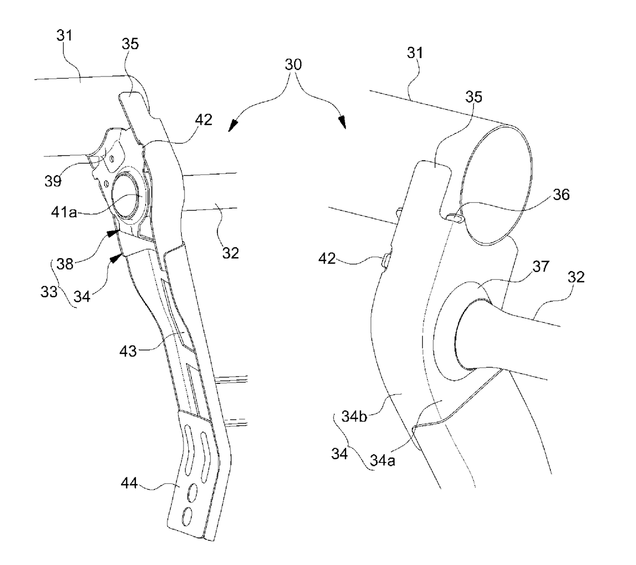
[0069]In FIG. 9, there is illustrated a schematic layout structure of a cowl cross bar provided with a center supporter according to a third embodiment. In FIGS. 10 and 11, there are illustrated a detailed structure of the center supporter and a coupling structure between the main cross bar and a sub-cross bar, according to the third embodiment.

[0070]As shown in FIG. 9, in the cowl cross bar 30, a main cross bar 31 and a sub-cross bar 32 may be disposed such that the sum of the radius of the main cross bar 31 and the radius of the sub-cross bar 32 is greater than the distance between a diametric center of the main cross bar 31 and a diametric center of the sub-cross bar 32.

[0071]As such, in the case of the cowl cross bar 30 having the layout structure of the main cross bar 31 and the sub-cross bar 32 that are disposed such that the diametric centers thereof are positioned eccentrically from each other, a center supporter 33 which has a structure shown in FIGS. 10 and...


PUM


Abstract

A cowl cross bar for a vehicle comprising a main cross bar disposed in front of a driver's seat in a transverse direction of the vehicle, a sub-cross bar disposed in front of a passenger seat in the transverse direction of the vehicle, and a center supporter configured to couple the main cross bar and the sub-cross bar to each other such that diametric centers thereof are disposed eccentrically relative to each other, the center supporter may include a main center support bracket provided with a connector to which a longitudinal end of the sub-cross bar is fixed, and a sub-center support bracket fixed to the main center support bracket, and having an insert hole through which a longitudinal end of the main cross bar is fixed to the sub-center support bracket.

Description

CROSS-REFERENCE TO RELATED APPLICATION[0001]The present application claims priority to Korean Patent Application No. 10-2016-0067929 filed Jun. 1, 2016, the entire contents of which is incorporated herein for all purposes by this reference.BACKGROUND OF THE INVENTIONField of the Invention[0002]The present disclosure relates to a cowl cross bar for a vehicle. More particularly, it relates to a cowl cross bar for a vehicle which is configured such that the coupling structure between a main cross bar in front of a driver's seat and a sub-cross bar in front of a passenger seat is improved, whereby the stiffness of the cowl cross bar can be enhanced.Description of Related Art[0003]Generally, a cowl cross bar is provided in the front of a vehicle to support a steering apparatus such that the steering apparatus is fixed to a vehicle body. The cowl cross bar is directly mounted to the vehicle body in such a manner that cowl cross bar is disposed perpendicular to a steering column of the ste...

Claims


Application Information

Patent Timeline
IPC IPC(8): B62D7/22B62D27/02B62D25/14B62D29/00
CPCB62D7/224B62D29/008B60Y2410/121B62D27/02B60Y2410/124B62D25/145B62D25/081B62D21/08
Inventor KONG, BYUNG SEOKJANG, JUNG YOON
Owner HYUNDAI MOTOR CO LTD
Why Eureka
Try Eureka