

Antenna-feeder device and antenna
a technology of antenna and feeder device, which is applied in the direction of antennas, electrical equipment, etc., can solve the problems of increasing the size of the antenna system, disfiguring the architectural image of buildings, and the large lateral size of the antenna itsel
- Summary
- Abstract
- Description
- Claims
- Application Information
AI Technical Summary
Benefits of technology
Problems solved by technology
Method used
Image

Examples
Embodiment Construction
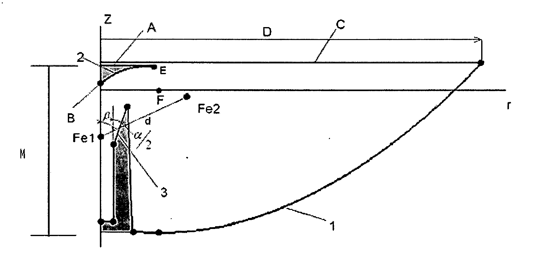
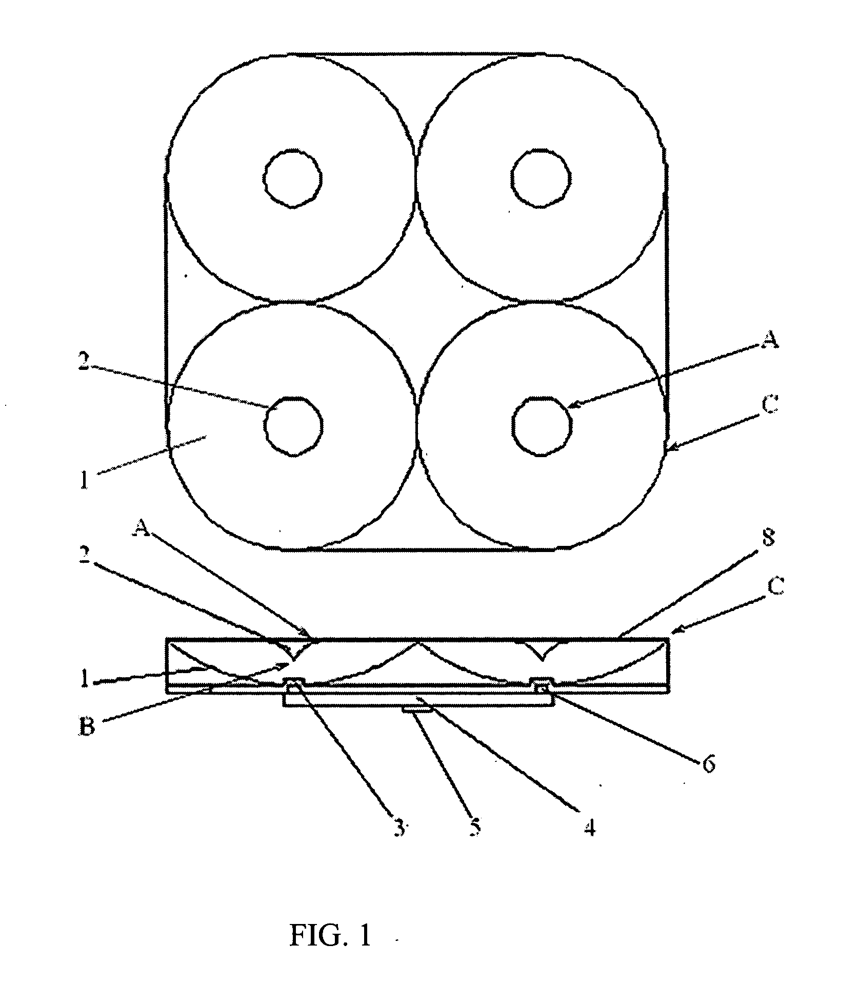
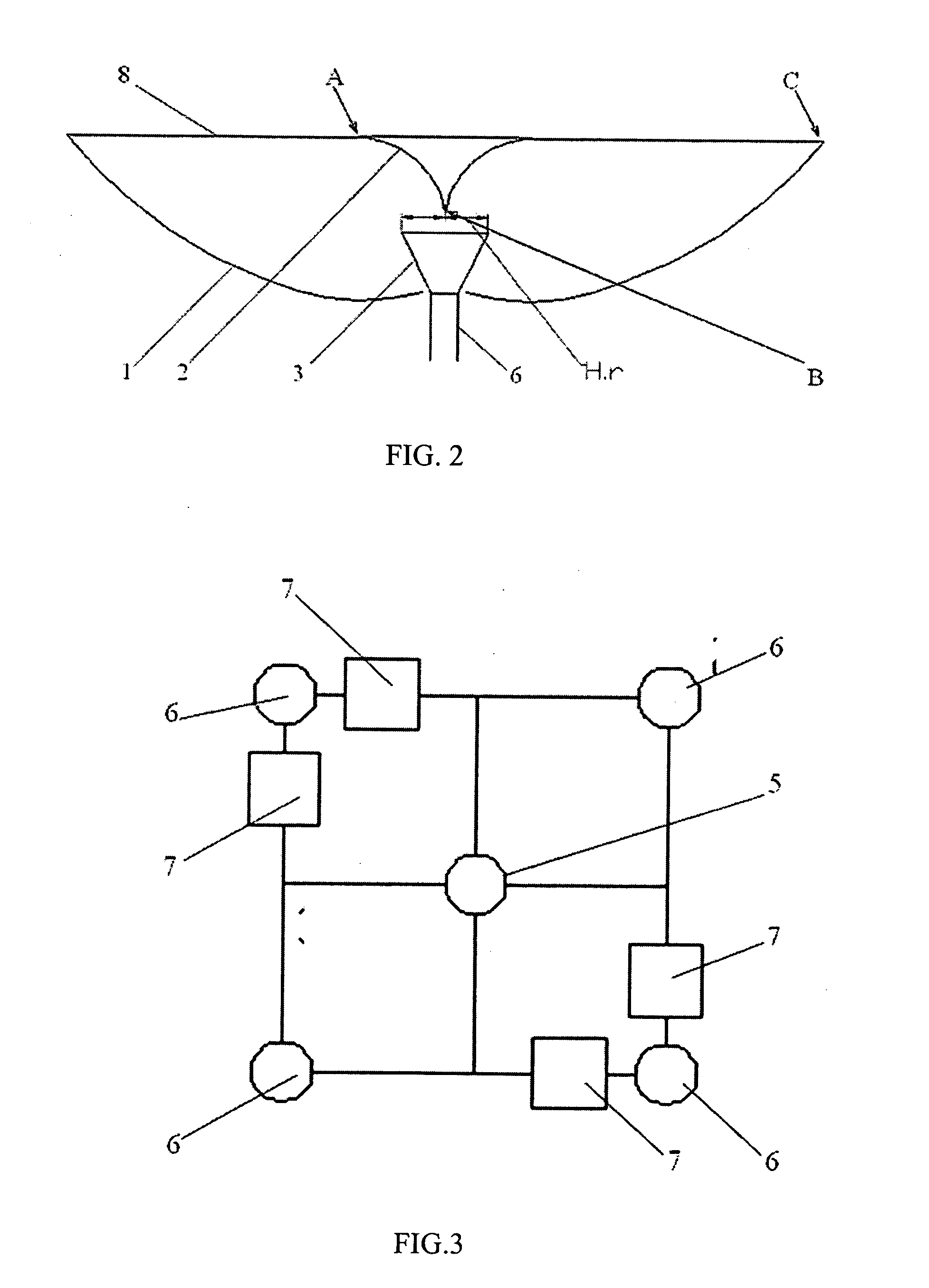
[0120] Antenna-feeder device (FIG. 1) comprises four dual reflector antennas situated in one plane and one feeding device. A main reflector 1 of each dual reflector antenna is made with parabolic generatrix and a sub-reflector 2 of each dual reflector antenna is made with elliptic generatrix (FIGS. 1, 2). The sub-reflector 2 has circle A and vertex B. Vertex B is faced to the main reflector 1 and situated between circle A and the main reflector 1. Radiator 3 for each dual reflector antenna is situated on rotation axis (longitudinal symmetry axis Z) in the main reflector 1 base between the main reflector 1 and the sub-reflector 2. Feeding device 4 (FIG. 1) is assigned for connection with input 5 to receiving and / or transmitting device. Four outputs 6 of feeding device 4 are connected to radiators 3 of each dual reflector antenna correspondingly. Feeding device is made of power dividers where each divider is made in form of single mode transmission lines junction and each divider is m...
PUM
 Abstract
Description
Claims
Application Information