Medical instrument and method of cutting a tissue using the medical instrument

a technology of medical instruments and tissue, applied in the field of medical instruments, can solve the problems of collateral damage, lengthening procedure times, and increasing the limitations of this basic instrument configuration

Inactive Publication Date: 2015-11-17
STEWART & STEIN ENTERPRISES
View PDF3 Cites 0 Cited by
  • Summary
  • Abstract
  • Description
  • Claims
  • Application Information

AI Technical Summary

Benefits of technology

[0016]In one form, the first leg of the U-shaped portion has a free end. The first component is advanced selectively towards and away from the free end of the first leg to respectively decrease and increase the width of the entryway.
[0022]In one form, at least one discrete component is provided on at least one of the first and second legs and configured to inhibit sliding of tissue against and along the at least one of the first and second legs.

Problems solved by technology

While it is known to manipulate tissue through an instrument having a hooked distal end at which a cutting blade is located, heretofore there have been a number of limitations associated with this basic instrument configuration.
This can lead to collateral damage around the intended site and may lengthen procedure times and potentially necessitate internal treatment of tissue to repair inadvertently cut regions thereof.
While use of a cannula may shield tissue from the cutting blade as the instrument is initially directed towards an operating site, the potential for collateral damage arises again, after the cannula is removed, as a surgeon relocates the hooked end to different sites as a procedure may demand.
Further, damage may be inflicted at the conclusion of a procedure as the instrument, with the exposed cutting blade, is withdrawn.
Additionally, once the desired tissue portion is strategically situated in the cutting space preparatory to effecting a cut, the tissue has a tendency to escape from the cutting space.
This may necessitate repeating steps, which adds undesirably to the overall time necessary to perform the procedure.
Further, uncontrolled tissue movement relative to the hooked end may make it difficult, or impossible, to precisely locate a cut.

Method used


Image

  • Medical instrument and method of cutting a tissue using the medical instrument
  • Medical instrument and method of cutting a tissue using the medical instrument
  • Medical instrument and method of cutting a tissue using the medical instrument

Examples


Embodiment Construction

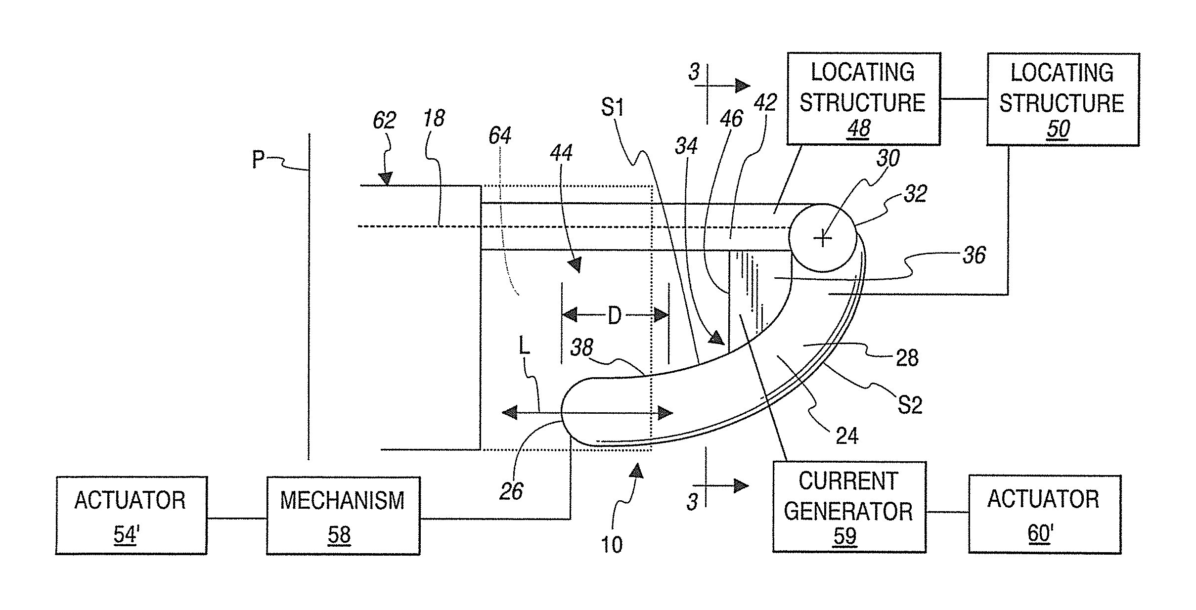
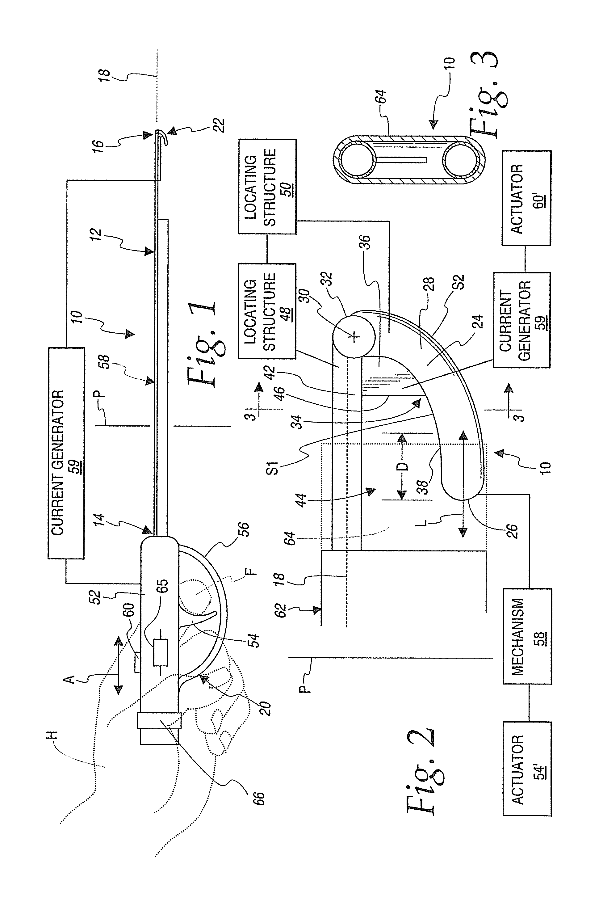
[0066]In FIGS. 1-11, a medical instrument, according to the present invention, is shown at 10. The medical instrument 10 consists of an elongate frame 12 with proximal and distal ends 14, 16, respectively, spaced in a lengthwise direction along a central axis 18 of the frame 12.

[0067]An operating assembly 20 is provided at a proximal region of the frame 12. A working assembly 22 is provided at a distal region of the frame 12.

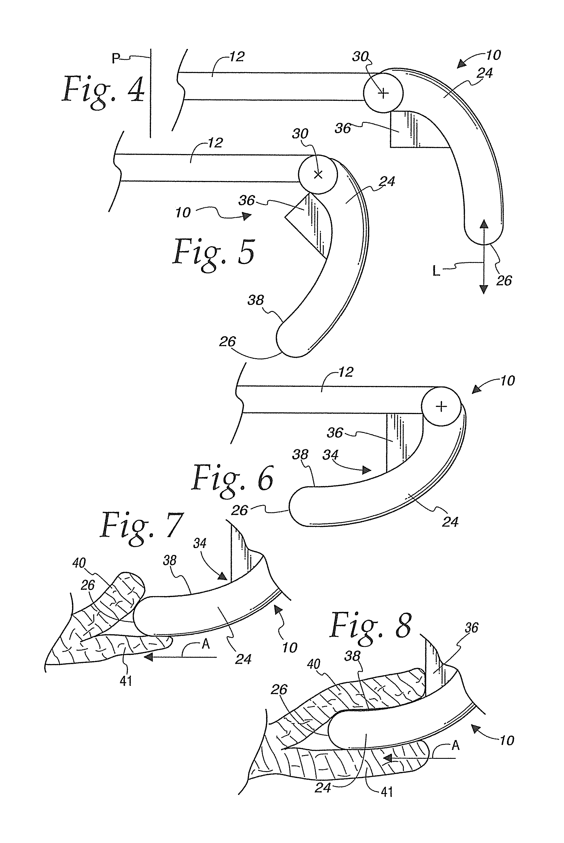
[0068]The working assembly 22 consists of a cantilevered tip 24 with a free end 26. The tip 24 has a body 28. The working assembly 22 is reconfigurable by an operator through the operating assembly 20 by selectively reorienting the tip 24 relative to the frame 12. In the depicted embodiment, the tip body 28 is movable relative to the frame 12 around a fixed axis 30.

[0069]The various contemplated positions for the tip 24 can also be clearly described relative to a reference plane P that extends through the frame 12 orthogonally to the central axis 18 at a locatio...


PUM


Abstract

A medical instrument having an elongate frame with proximal and distal ends spaced in a lengthwise direction along a central axis. A working assembly at a distal region of the frame has a U-shaped portion defined by first and second legs meeting at a base. The U-shaped portion defines a cutting space. The working assembly further has a cutting assembly with a sharp edge in the cutting space. The working assembly and elongate frame are configured so that a tissue entryway is defined through which a tissue can be advanced to be moved into the cutting space and against the sharp edge. The medical instrument further has a first assembly configured to be operated to vary a configuration of the entryway.

Description

CROSS-REFERENCE TO RELATED APPLICATIONS[0001]This application is a continuation-in-part of, and claims priority to, provisional application U.S. Ser. No. 61 / 953,063, filed Mar. 14, 2014, and U.S. Ser. No. 13 / 889,561, filed May 8, 2013, both of which are hereby incorporated by reference in their entirety.BACKGROUND OF THE INVENTION[0002]1. Field of the Invention[0003]This invention relates to medical instruments and, more particularly, to a medical instrument for repositioning and cutting a human body tissue at an operating site. The invention is also directed to a method of using such a medical instrument.[0004]2. Background Art[0005]In many surgical procedures, tissue is required to be controllably dissected. This dissection is commonly effected using cauterization. Oftentimes, the dissection is effected using only a blade with a sharp cutting edge that is drawn against the region of the tissue to be cut.[0006]While it is known to manipulate tissue through an instrument having a ho...

Claims


Application Information

Patent Timeline
Patent Type & Authority Patents(United States)
IPC IPC(8): A61B17/32A61B17/3205A61B18/14A61B18/00
CPCA61B17/3205A61B18/148A61B2017/320044A61B2018/00595A61B2018/00601A61B2018/1412A61B2018/1422A61B17/320016A61B17/3209A61B2017/2927A61B2017/320064
Inventor STIEN, KARL E.STEWART, NATHANIEL J.
Owner STEWART & STEIN ENTERPRISES
Why Eureka
Try Eureka