

Dielectric lens cone radiator sub-reflector assembly
a radiator and dielectric lens technology, applied in the field of microwave dual reflector antennas, can solve the problems of increasing the overall manufacturing cost, rf signal path blockage by the sub-reflector along the boresight of the reflector antenna,
- Summary
- Abstract
- Description
- Claims
- Application Information
AI Technical Summary
Benefits of technology
Problems solved by technology
Method used
Image

Examples
Embodiment Construction
[0017]The inventors have recognized that improvements in cone radiator sub-reflector assembly designs utilizing unitary dielectric blocks typically require manufacture of the dielectric block by machining, due to the increased size and complexity of these designs.
[0018]When injection molding and / or casting methods of manufacture are attempted on the prior dielectric block type cone radiator sub-reflector assembly designs, the increased size may create issues with the setting of the dielectric polymer material, such as voids, cracks, surface sink, dimensional bends and / or sagging. Further, where the designs utilize features that inhibit mold separation, such as overhanging and / or close proximity opposing edges, the required mold, if possible at all, may become too complex to be cost effective.
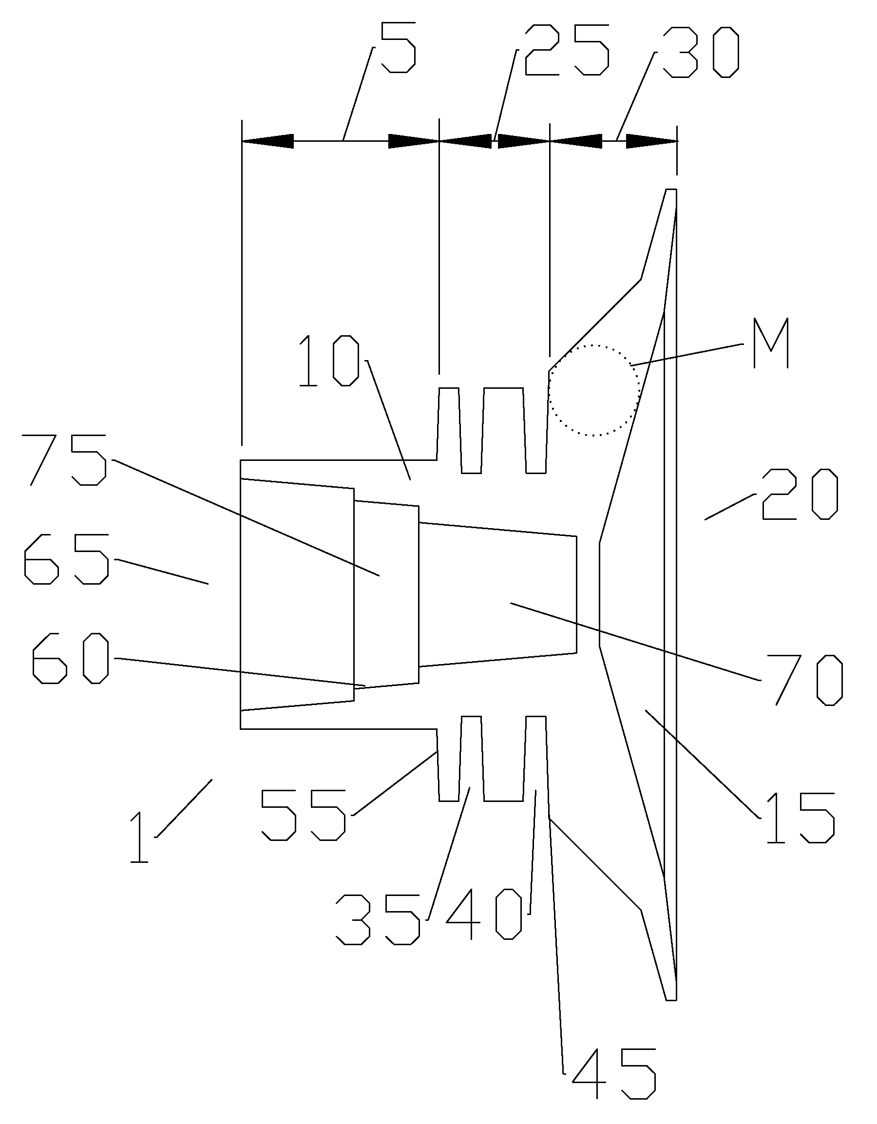
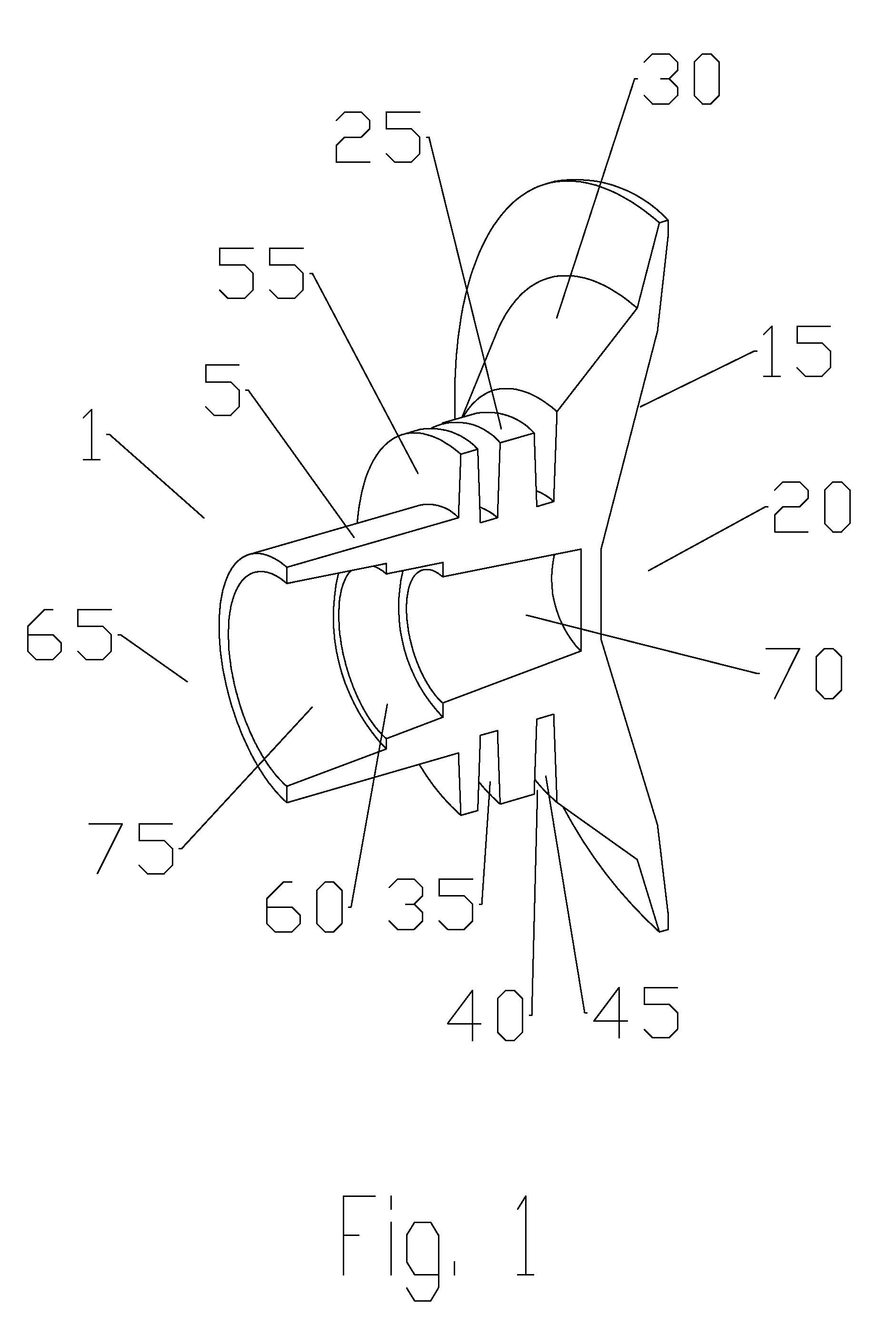
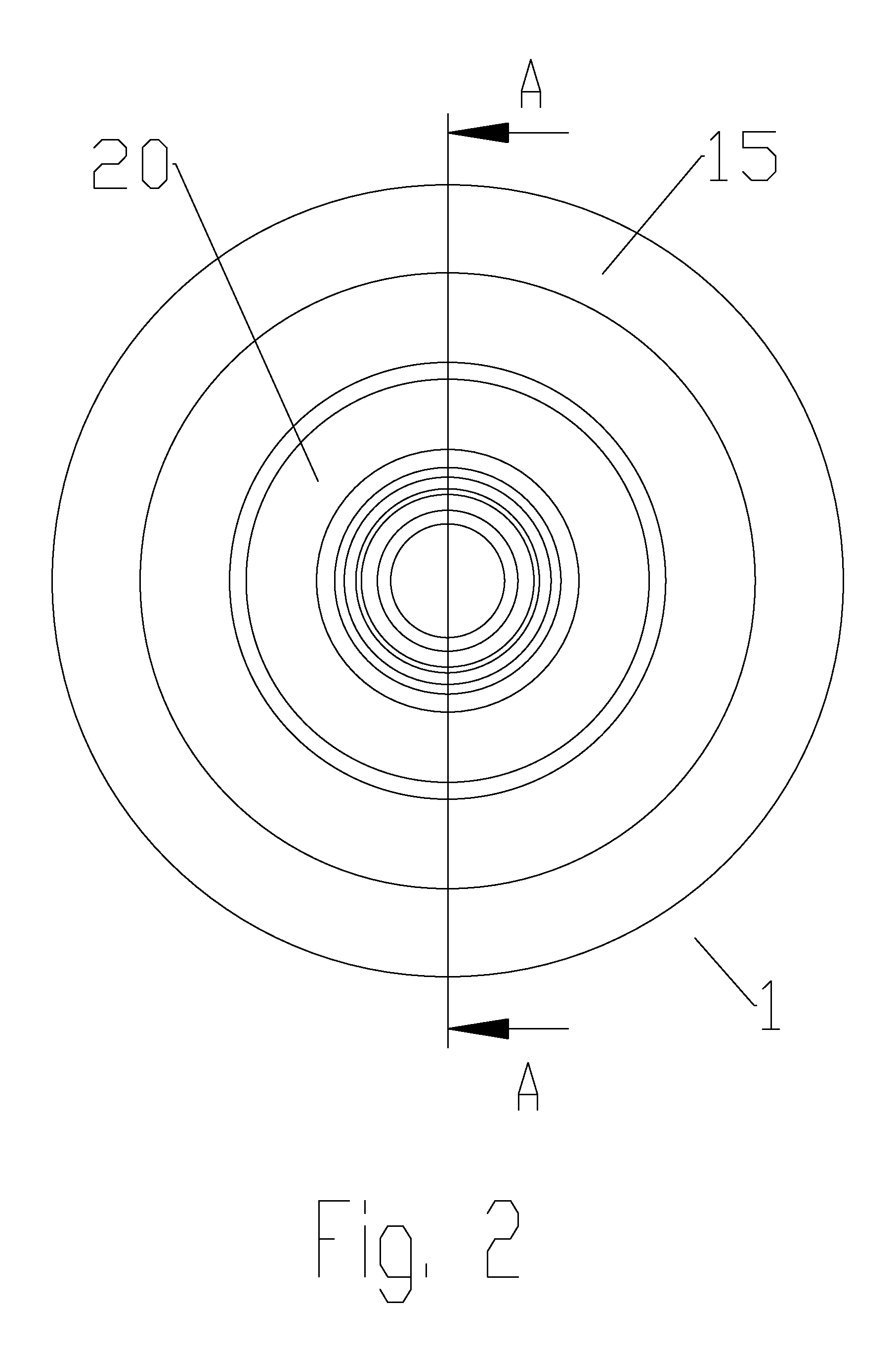
[0019]As shown in FIGS. 1-6, a cone radiator sub-reflector assembly 1 may be configured to couple with the end of a feed boom waveguide at a waveguide transition portion 5 of a unitary dielectri...
PUM
| Property | Measurement | Unit |
|---|---|---|
| outer diameter | aaaaa | aaaaa |
| diameter | aaaaa | aaaaa |
| inner diameter | aaaaa | aaaaa |
Abstract
Description
Claims
Application Information