
Method and systems using prediction of outcome for launched objects

a technology of prediction and outcome, applied in the field of methods and systems using prediction of outcome for launched objects, can solve the problem of easy errors in the accuracy of such prediction, and achieve the effect of improving prediction accuracy and reducing errors

Inactive Publication Date: 2007-07-19
LINDSAY LTD
View PDF3 Cites 128 Cited by
  • Summary
  • Abstract
  • Description
  • Claims
  • Application Information

AI Technical Summary

Benefits of technology

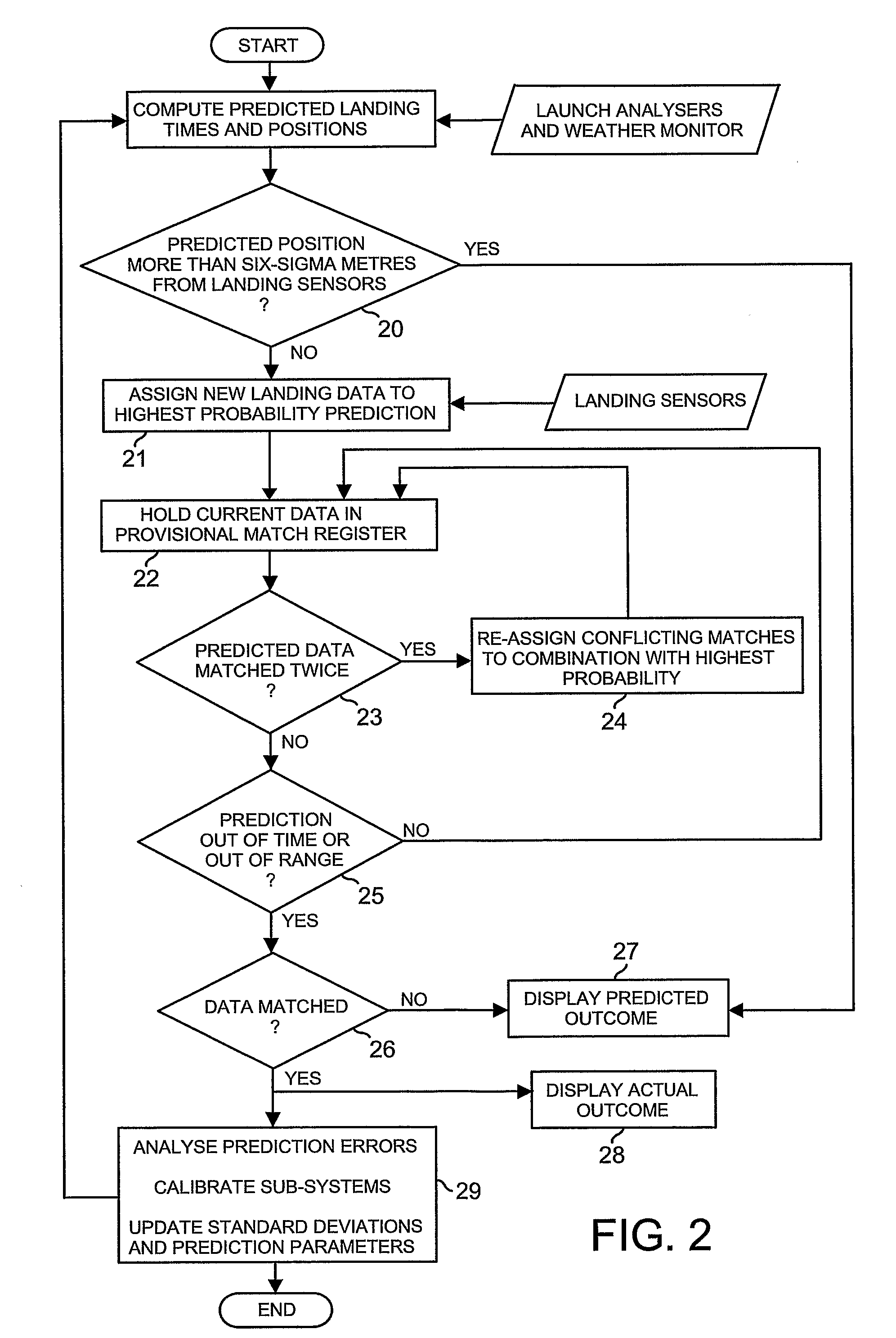
[0006] The method and system of the invention is especially applicable to providing representations of the outcome of successive strikes of a golf ball, for example in the context of a golf range. In this respect, measurements of the launch velocity and spin vectors of a ball can be used to predict its ensuing flight-carry and -duration, its landing speed, landing backspin, angle of descent and subsequent bounce and roll. However, the accuracy of such prediction is very prone to errors arising from inaccuracies in the flight model, the bounce and roll model and the launch measurements and also variations in atmospheric conditions (e.g. wind speed, rain, temperature and pressure) and also in the rebound and friction properties of the landing terrain. The method and system of the present invention enable a significant improvement in prediction accuracy to be achieved by sensing the actual outcomes realised in relation to some shots and from the way in which these differ from the predicted outcomes computed for those same shots, correct the computation process adaptively to reduce error.
[0007] The “end-of-flight” parameters may be predicted and measured, namely, the carry-length, the direction and the flight duration. One possible means of achieving the measurement of actual carry distance and deviation and the flight duration is disclosed in WO-A-9201494 which describes the use of geophones distributed around a reception area to sense the impact of the ball as it lands. Signals corresponding to the time of arrival of the impact vibration at proximate geophones are recorded and, by analysing the time differences in these signals at different geophones, the position and time of impact can be accurately measured.
[0013] Another way of creating a detection plane is to arrange that the TXRX axis is parallel to the length axis of the slit-aperture. Provided the TXRX separation is small compared to the length of the slit-aperture, the fields of view for the light emitting means and light-sensing means are nearly identical. The detection plane thus formed comprises the common field of view. An advantage of this type of detection plane compared with that previously described, is that more light is emitted into the detection plane and more light is reflected back from the detection plane because the entire field of view is used. However, the width of the detection plane increases with range as it spreads out into a wedge shaped volume. This can be corrected using a cylindrical lens, so that the detection plane is again of uniform thickness (equal to the width of the slit-aperture) or nearly so. This method of forming the detection plane improves its sensitivity and operating range.
[0016] Means may be provided to enhance the detection of a retro-reflector in the presence of unwanted reflections from other parts of the moving article by placing a first light polarizing filter in front of the light emitter and a second light polarizing filter in front of the co-acting light sensor. Light reflected from the retro-reflector has its plane of polarization rotated 90 degrees (or theoretically so). The two filters are oriented so that the planes of polarization are at 90 degrees to one another (or at optimum cross orientation), so only the polarized target-reflected light is allowed to pass through the said second polarizing filter and into the light sensor. When the polarized emitted light strikes other (non-retro-reflective) surfaces of the object being detected or internal surfaces in the measurement apparatus, its plane of polarization is not rotated, and the returned beam is blocked from entering the sensor. A second co-acting light sensor may be provided on the obverse side of the light emitter with a polarized filter aligned with the plane of polarisation of the emitted light. This is insensitive to reflected light from retro-reflective surfaces but sensitive to other reflective surfaces, and provides two signals, for example, one responsive to retro-reflective dots on the surface of a golf ball and the second responsive to reflections from the ball surface alone.
[0017] Various types of polarizing filters may be used such as Rochon, Brewster or dichroic polarizers. One type of dichroic polarizer that is advantageously useful at infrared wavelengths is the wire-grid polarizer. Wire-grid polarizers are very expensive to manufacture compared to the much more common sheet polarizers (based on modified polyvinyl alcohol iodine) but, in the present context, the dimensions of the filters are exceptionally small so it is economic to use wire-grids. Since both the emitter and sensor devices in a TXRX pair share a common focusing lens and / or slit-aperture, the filters are preferably fabricated on or very close to the active areas of these devices. The active areas are very small (e.g. 0.1 to 1.0 square millimeters) so the polarizing filters are also very small. Judicious design of the wire-grids and associated conductors can also help to reduce radio frequency interference in the sensor signals generated by the relatively high power emitter drive signals. Anticipating future developments in light emitter and sensor devices, the emitter and / or sensor may transmivrespond in one plane of polarization without need of additional filters.

Problems solved by technology

However, the accuracy of such prediction is very prone to errors arising from inaccuracies in the flight model, the bounce and roll model and the launch measurements and also variations in atmospheric conditions (e.g. wind speed, rain, temperature and pressure) and also in the rebound and friction properties of the landing terrain.

Method used


Image

  • Method and systems using prediction of outcome for launched objects
  • Method and systems using prediction of outcome for launched objects
  • Method and systems using prediction of outcome for launched objects

Examples


Embodiment Construction

[0037] Reference axes X, Y and Z are shown for convenience in conveying orientation, where this is appropriate in certain of the figures to which reference is made in the following description. In this respect, the Z-axis is vertical and points upwards, the Y-axis is horizontal and points downrange (i.e. along the general line of flight of a golf shot), and the X-axis is orthogonal to the Y- and Z-axes and points in the general ‘heel-to-toe’ direction of a club head at ball address.

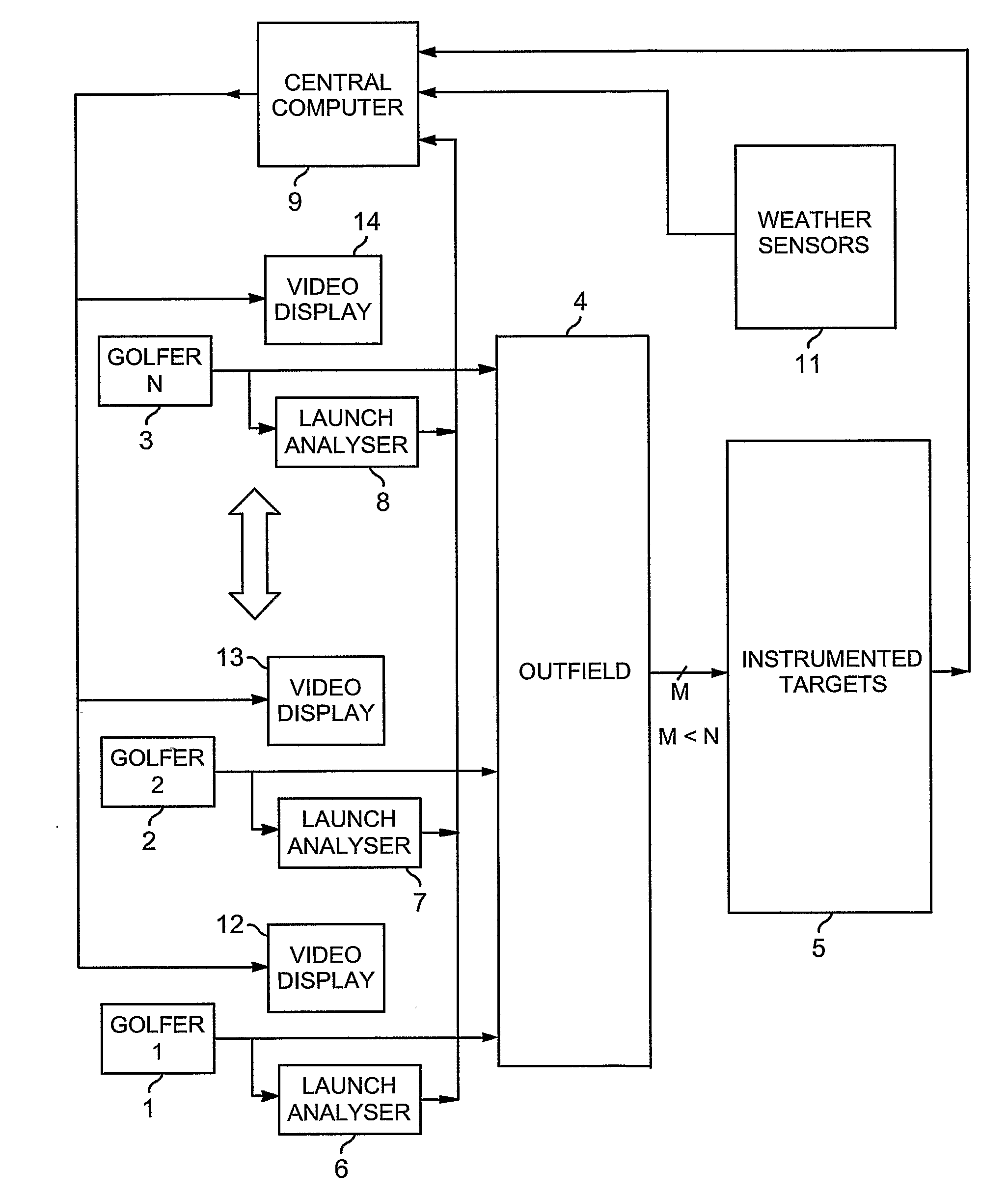
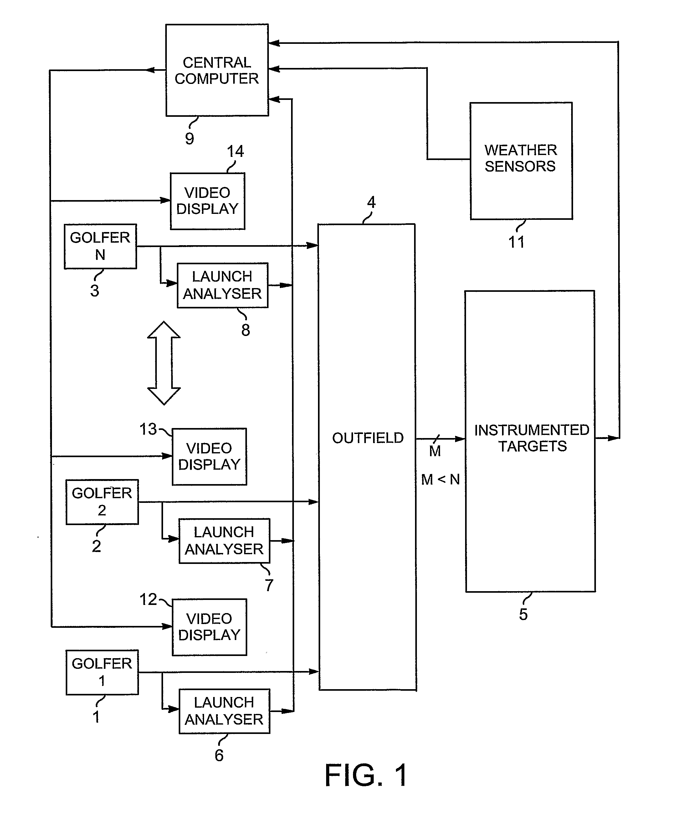
[0038] The block diagram of FIG. 1 outlines the top level system for a golf range facility where several golfers hit golf balls into the same general area. Blocks representing first, second and Nth golfers using the range are show as 1, 2 and 3 respectively. The golfers launch golf balls downrange onto the outfield 4 at random times and with random distances and direction, and some of the balls land on instrumented targets 5. In a first version of the instrumented target, the “end of flight” or “end of c...


PUM


Abstract

Each golfer (1-3) on a golf range (4) has an individual display (12-14) showing at least a predicted outcome of each of his / her shots, and a launch-analyser (6-8) to measure velocity vectors of the ball and / or club at strike for central-computation (9) of the prediction. Vibration and piezo-cable sensors (54,55;68,69) at instrumented targets (5;41-45,47) distributed throughout the range (4), detect the presence of balls arriving in their respective locations for matching with launched balls using the computed predictions and probability; active or passive radio-frequency identification and location of balls may also be used. Where a match is found, error between predicted and actual outcome is applied to adaptive correction of the prediction-computing process, and the actual outcome is displayed to the golfer instead of the prediction. Ball and / or club velocity vectors, and ball spin, at launch are measured from light changes occurring in detection planes (96,97;105;114-117;134;144-146) defined by slit apertures (94,95;104), and resulting from retro-reflection from ball (91;110;131) and / or club (130).

Description

[0001] This application is a national stage completion of PCT / GB2005 / 000611 filed Feb. 18, 2005 which claims priority from British Application Serial No. 0423500.8 filed Oct. 22, 2004, which claims priority from British Application Serial No. 0414028.1 filed Jun. 23, 2004, which claims priority from British Application Serial No. 0412583.7 filed Jun. 5, 2004, which claims priority from British Application Serial No. 0403561.4 filed Feb. 18, 2004. FIELD OF THE INVENTION [0002] This invention relates to methods and systems using prediction of outcome for launched objects. BACKGROUND OF THE INVENTION [0003] According to one aspect of the present invention there is provided a method for deriving representations of the individual outcomes of launching objects into an area that contains a plurality of mutually-spaced object-sensing means, wherein each sensing means detects the presence of any of the launched objects that arrive in the location of that respective sensing means, a predictio...

Claims


Application Information

Patent Timeline
IPC IPC(8): A63B69/36A63B43/00F41J5/056F41J5/14G01S17/58G01S17/66G01S17/74G01S17/86G01S17/875G01S17/88G01S17/89
CPCA63B24/0021G01S17/89A63B69/002A63B69/3658A63B2024/0031A63B2024/0037A63B2225/30A63B2225/54A63B2243/0066G01S17/023G01S17/58G01S17/66G01S17/74G01S17/875G01S17/88A63B43/00G01S17/86
Inventor LINDSAY
Owner LINDSAY LTD
Learn More