Optical lens system for camera

a technology of optical lens and camera body, which is applied in the field of optical lens system for cameras, can solve the problems of reducing affecting the use of the optical lens system of the camera, and affecting the use of the optical lens system by the user, so as to reduce the application of the product, reduce the width, and increase the overall length of the product

Active Publication Date: 2018-01-16
SEMYUNG UNIV IND ACADEMIC COOPERATION FOUND
View PDF19 Cites 1 Cited by
  • Summary
  • Abstract
  • Description
  • Claims
  • Application Information

AI Technical Summary

Benefits of technology

[0011]According to an embodiment of the present invention, the present invention aims to provide an optical lens system for camera in which a switching aperture is further disposed at the position where an aperture stop area is defined to perform a series of switching operations, such as increasing or decreasing its width of opening for width of transparent area) so that the light beam from the object has an increased or decreased width, thereby allowing a captured image or magnified image corresponding to the object to be selectively formed on the object image formation member.
[0012]Therefore, the optical lens system for camera may easily address various issues (e.g., a significant deterioration of the quality competitiveness of the product or reduction in application of the product) that the manufacturer or user of the electronic device may suffer due to a failure to form magnified images by allowing for flexible addition of a series of magnified image formation functions (i.e., object magnifying function) as well as its own basic captured image formation function even without, e.g., difficulty in attaching or detaching an additional lens system for magnified image or increase in the overall length of the product.
[0031]Accordingly under an environment where the present invention is implemented, the optical lens system for camera may flexibly add a series of magnified image formation functions (i.e., object magnifying function) as well as its own basic captured image formation function even without, e.g., difficulty in attaching or detaching an additional lens system for mainlined image or increase in the overall length of the product.
[0032]Therefore, the manufacturer or user of the electronic device may easily avoid various issues (e.g., a significant deterioration of the quality competitiveness of the product or reduction in application of the product).

Problems solved by technology

Therefore, the user of the electronic device may get in trouble in using the camera optical lens system for magnifying object (Of course, as shown in FIG. 2, as the object P is brought closer to the optical lens system 10, the light beams 19 from the object P would form a dispersed focus with a larger width H2.)
However, the conventional techniques take such a raw approach as independently attaching or detaching a separate lens system for magnifying object from a camera optical lens system, which renders the same difficult to carry and use along with the electronic device.
Due to a failure to perform the magnified image formation function, the manufacturer or user of the electronic device suffers from various issues (e.g., a deterioration of quality competitiveness of the electronic device or reduction in application of the electronic device).
Therefore, the optical lens system for camera may easily address various issues (e.g., a significant deterioration of the quality competitiveness of the product or reduction in application of the product) that the manufacturer or user of the electronic device may suffer due to a failure to form magnified images by allowing for flexible addition of a series of magnified image formation functions (i.e., object magnifying function) as well as its own basic captured image formation function even without, e.g., difficulty in attaching or detaching an additional lens system for magnified image or increase in the overall length of the product.

Method used


Image

  • Optical lens system for camera
  • Optical lens system for camera
  • Optical lens system for camera

Examples


Embodiment Construction

[0045]Hereinafter an optical lens system for a camera according to the present invention is described in greater detail with reference to the accompanying drawings.

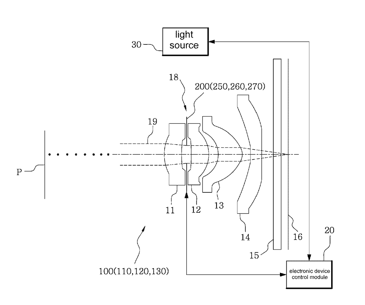
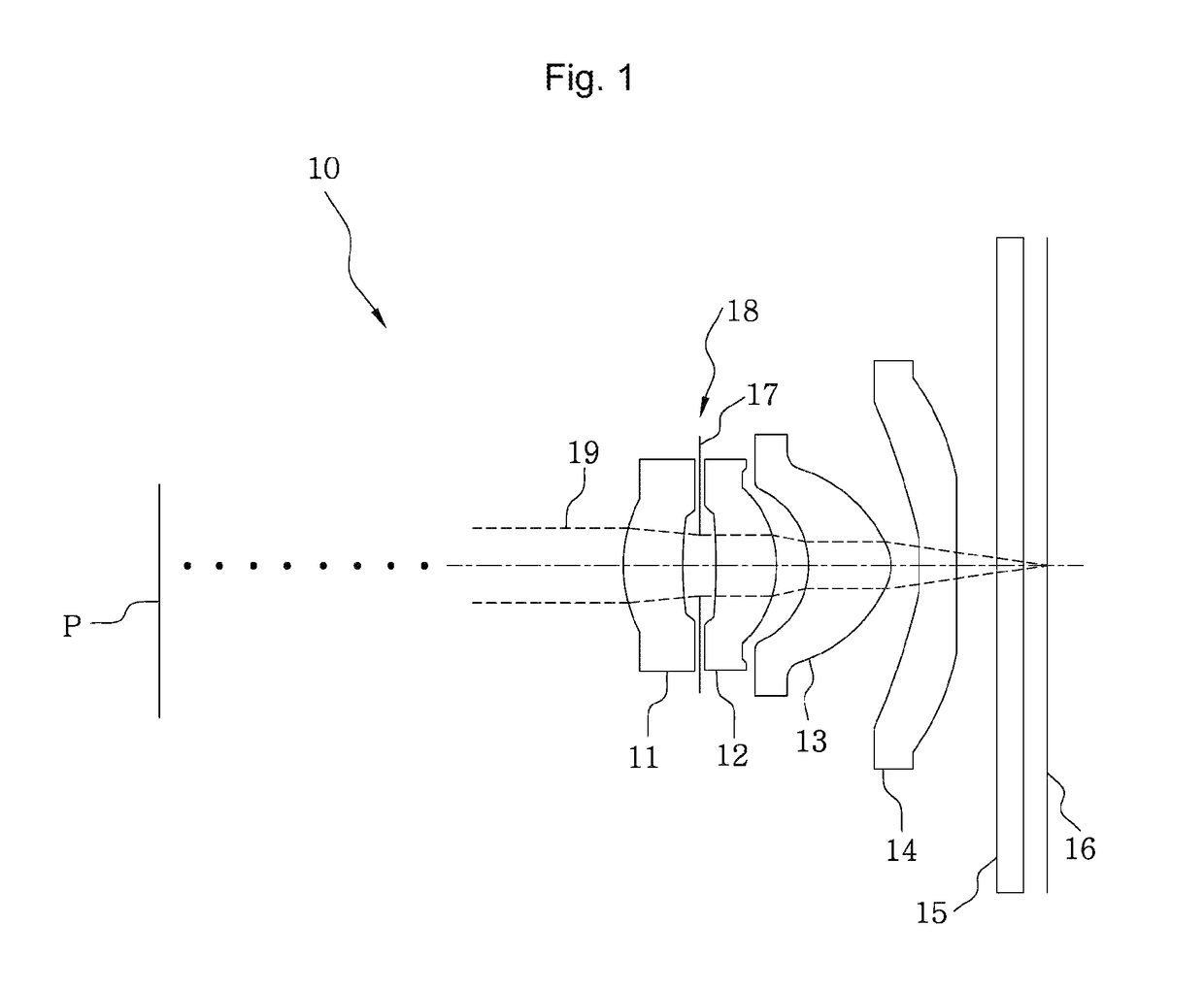
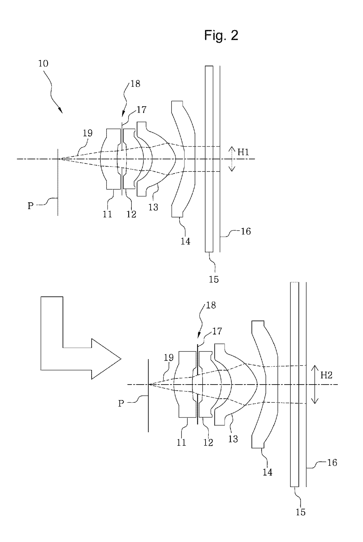
[0046]As shown in FIGS. 3 and 4, according to an embodiment of the present invention, an optical lens system 100 is systematically configured with an object image formation member 16 for forming a captured image corresponding to an object P, which has a CCD device or CMOS device for forming images disposed therein, optical lenses 11, 12, 13, and 14 arranged ahead of the object image formation member 16, an aperture stop area positioned in a front space of the optical lenses 11, 12, 13, and 14, gap spaces between the optical lenses 11, 12, 13, and 14, or a rear space of the optical lenses 11, 12, 13, and 14, and an optical filter 15 disposed before the object image formation member 16 to cut off unnecessary light beams (for reference, there may be one or more optical lenses 11, 12, 13, and 14. Here, in case there is one op...


PUM


Abstract

An optical lens system for photographing an object, according to an embodiment of the present invention, comprises an object image forming member for forming an image of the object, a light source for providing light to the object, optical lenses, an aperture stop area, and a switching aperture disposed in the aperture stop area. The switching aperture includes a base plate having, in the center thereof, an opening for an image to be taken, a blade having, in the center thereof, a pin hole for an image to be magnified such that a magnified image corresponding to the object is formed, and a variable connection member bent or straightened according to power supply to induce light incident from the object to form a photographed image via the opening for an image to be taken or form a magnified image via the pin hole for an image to be magnified.

Description

TECHNICAL FIELD[0001]The present invention relates to optical lens systems for cameras, and more specifically, to optical lens systems for cameras which are capable of flexibly performing a series of magnified image formation functions (i.e., object magnifying function) as well as basic captured image formation functions.DISCUSSION OF RELATED ART[0002]A recent remarkable development of electric / electronic technology leads to a sharp growth or spread of electronic devices (e.g., desktop computers, mobile phones, tablet PCs, game players, or laptop computers) that are equipped with an optical lens system for cameras (e.g., digital cameras) to carry out a series of camera functions in various manners.[0003]As shown in FIG. 1, an optical lens system 10 according to the prior art is systematically configured with an object image formation member 16 for forming a captured image corresponding to an object P, which has a CCD device or CMOS device for forming images disposed therein), optica...

Claims


Application Information

Patent Timeline
Patent Type & Authority Patents(United States)
IPC IPC(8): G03B9/02G03B9/04G03B15/03H04N5/225G03B17/12G03B19/16H04N5/232
CPCG03B9/02G03B9/04G03B15/03G03B19/16H04N5/2254H04N5/23296G03B17/12G03B2205/0053G02B13/004G02B15/10G02B5/005H04N23/55H04N23/69
Inventor CHO, SUNGGOO
Owner SEMYUNG UNIV IND ACADEMIC COOPERATION FOUND
Why Eureka
Try Eureka