Tunnel/wall unit

a technology of wall units and tunnels, applied in door/window fittings, building components, construction, etc., can solve problems such as gaps left between walls and exterior frames

Inactive Publication Date: 2007-09-06
RADIO SYST CORP
View PDF4 Cites 24 Cited by
  • Summary
  • Abstract
  • Description
  • Claims
  • Application Information

AI Technical Summary

Problems solved by technology

Instead, gaps may be left between

Method used


Image

  • Tunnel/wall unit
  • Tunnel/wall unit
  • Tunnel/wall unit

Examples


Embodiment Construction

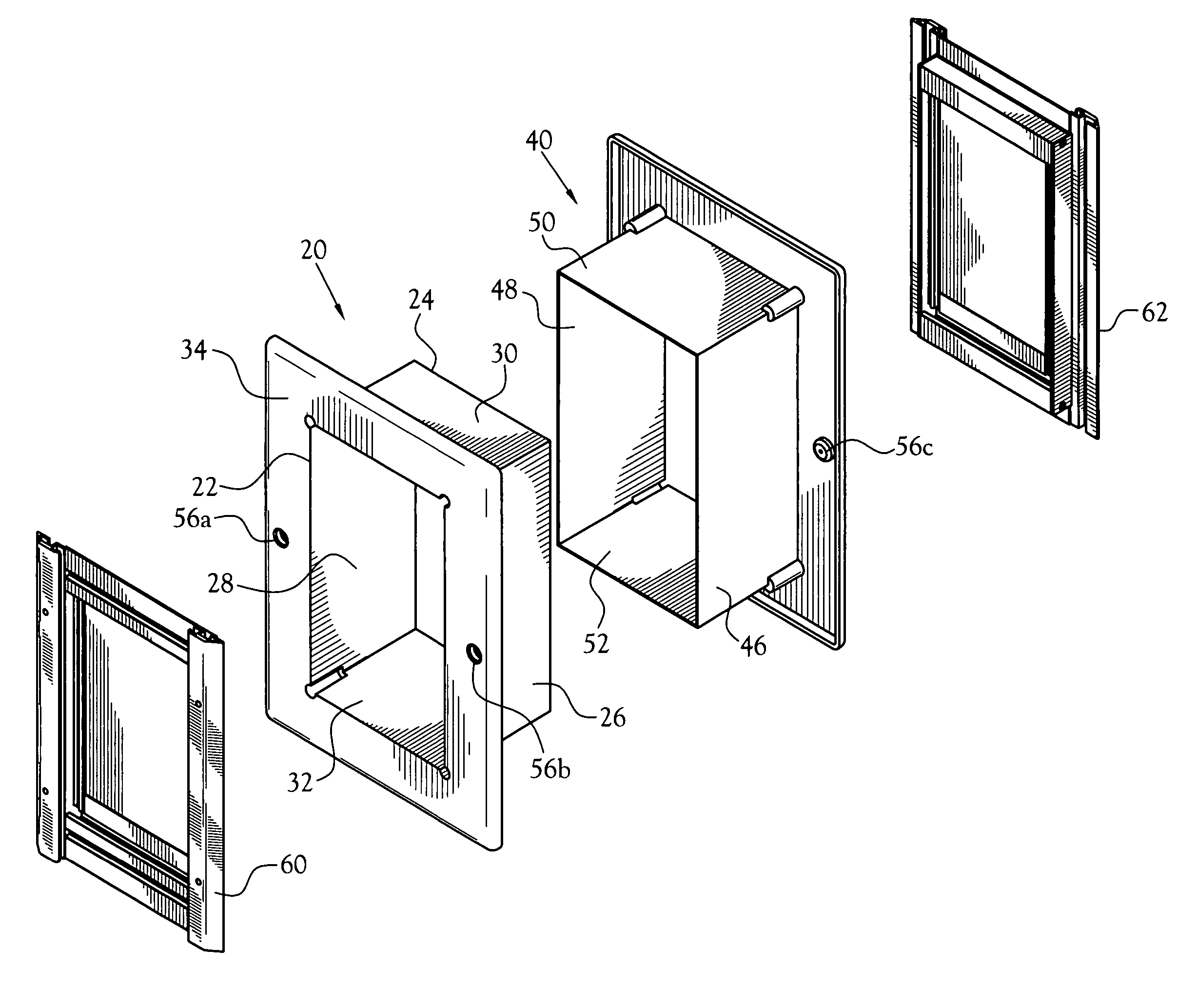
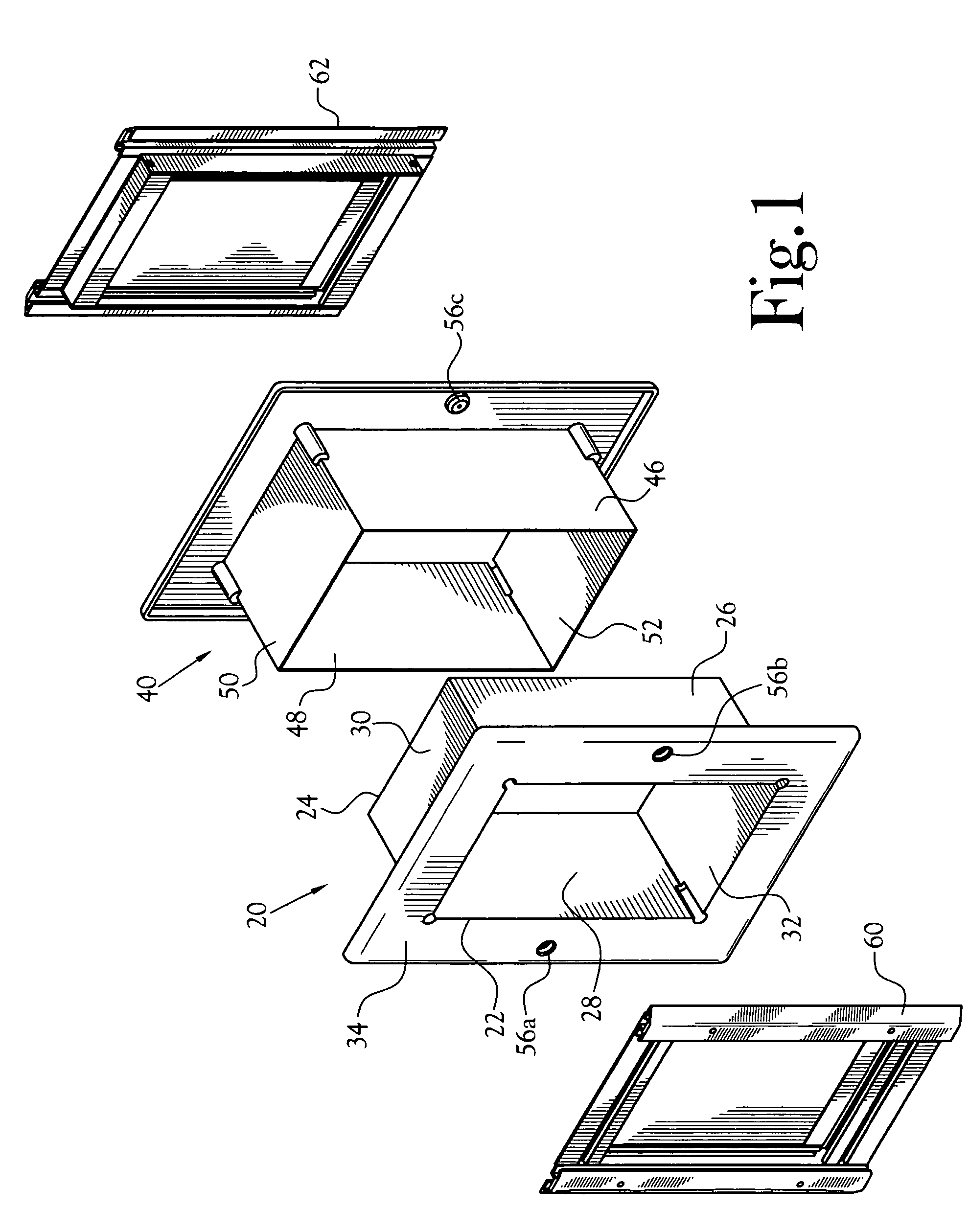
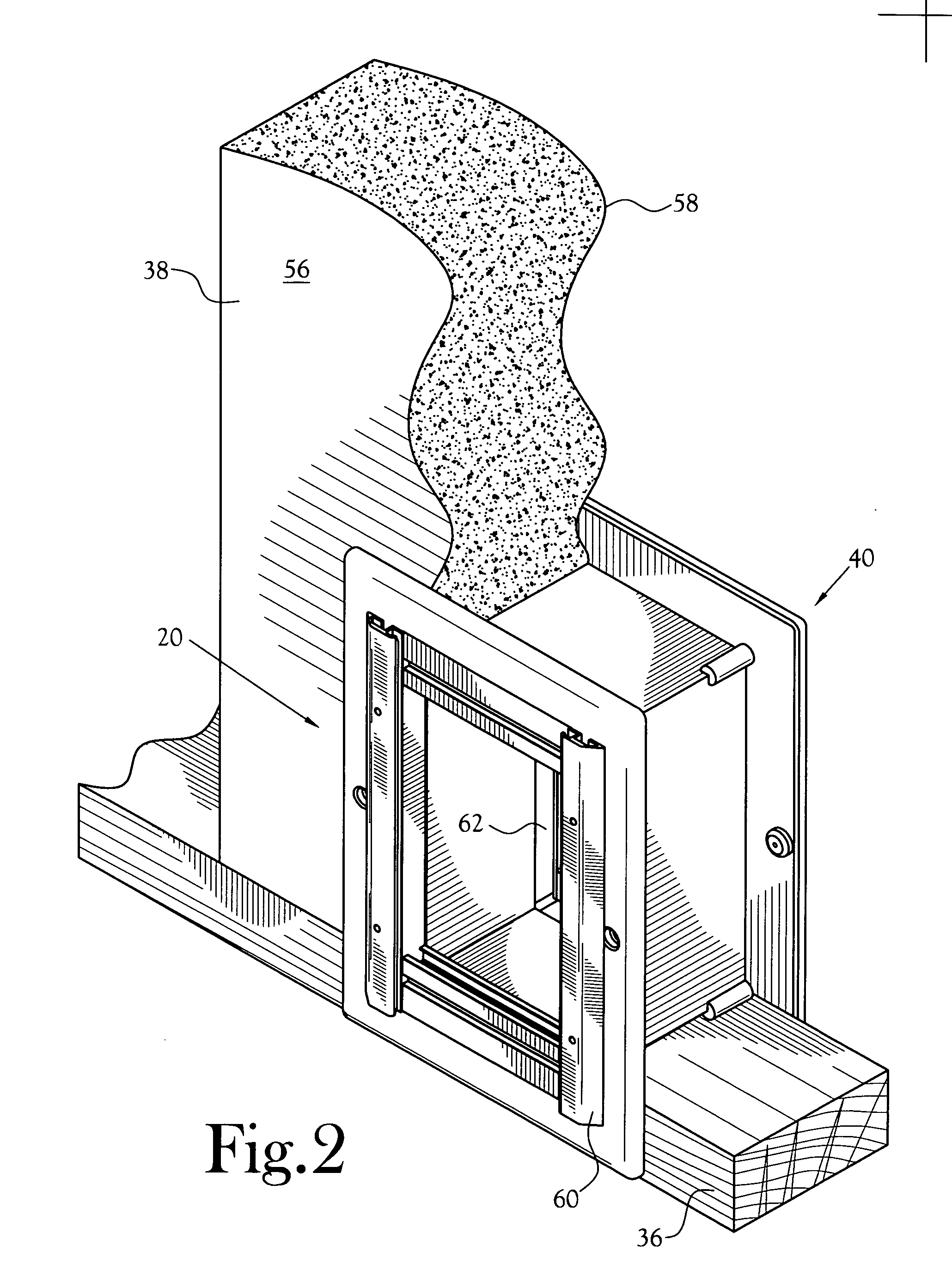
[0014] An apparatus for defining a tunnel through a wall is illustrated in the figures. A first elongated tubular section 20 includes an outboard end 22, a distal end 24. In the depicted embodiment, the first elongated tube section 20 is rectangular in cross-section. However, any cross-sectional shape may be employed with in the scope of the present invention. The dimensions of the cross-sectional shape are adapted to typical sizes of dogs and cats most likely to be using the tunnel. Additionally, the width of the first elongated tube section is preferably less than 14 inches in order to fit within typical stud spacing in a wall.

[0015] The first elongated tubular section 20 is cooperatively defined by a first side panel 26, an opposed second side panel 28, a top panel 30 and a bottom panel 32.

[0016] A first peripheral flange 34 extends around at least a portion of the periphery of the outboard end 22 of the first elongated tubular section 20. The width of the first peripheral flan...


PUM


Abstract

An apparatus for defining a tunnel through a wall includes a first elongated tubular section having an outboard end and a distal end. A first peripheral flange extends around at least a portion of the periphery of the outboard end of the first elongated tubular section. A second elongated tubular section has an outboard end and a distal end. A second peripheral flange extends around at least a portion of the periphery of the outboard end of the second elongated tubular section. The cross-sectional shape and dimensions of the second elongated tubular section are sized to slidingly telescope within the first tubular section when the distal end of the first tubular section is inserted through a hole in a first side of a wall and the distal end of the second tubular section is inserted through a coaxial hole in the opposing side of the wall.

Description

CROSS-REFERENCE TO RELATED APPLICATIONS [0001] Not Applicable STATEMENT REGARDING FEDERALLY SPONSORED RESEARCH OR DEVELOPMENT [0002] Not Applicable BACKGROUND OF THE INVENTION [0003] 1. Field of Invention [0004] This invention pertains to a pre-fabricated tunnel to allow passage through a wall, by a pet, for example. [0005] More particularly, this invention pertains to a slidingly telescoped tunnel for insertion through opposing sides of a wall. [0006] 2. Description of the Related Art [0007] Many efforts have been made to provide pets with access from one room to another room in a building or between the interior and exterior of a building. Most of these efforts have focused upon adding a smaller door within a larger door. In some cases, however, the building owner does not want to damage the main door, and instead cuts a hole in a wall and custom-builds a tunnel through the wall, along with a frame on each side of the wall. For a typical homeowner, the construction of a tunnel thr...

Claims


Application Information

Patent Timeline
IPC IPC(8): E05D15/48
CPCE06B7/32
Inventor GRIMMETT, ANDREW S.
Owner RADIO SYST CORP
Why Eureka
Try Eureka