
Portable electronic device

a portable electronic device and electronic device technology, applied in the direction of portable computer details, electric apparatus casings/cabinets/drawers, instruments, etc., can solve the problem of not being able to control the portable electronic device b>10/b> when in the palm of the user, and achieve the effect of improving the user experience and reducing the risk of accidental damag

Inactive Publication Date: 2007-09-20
HTC CORP
View PDF11 Cites 67 Cited by
  • Summary
  • Abstract
  • Description
  • Claims
  • Application Information

AI Technical Summary

Problems solved by technology

Thus, controlling the portable electronic device 10 when in a user's palm is not convenient.

Method used


Image

  • Portable electronic device
  • Portable electronic device
  • Portable electronic device

Examples


Embodiment Construction

[0011]The following description is of the best-contemplated mode of carrying out the invention. This description is made for the purpose of illustrating the general principles of the invention and should not be taken in a limiting sense. The scope of the invention is best determined by reference to the appended claims.

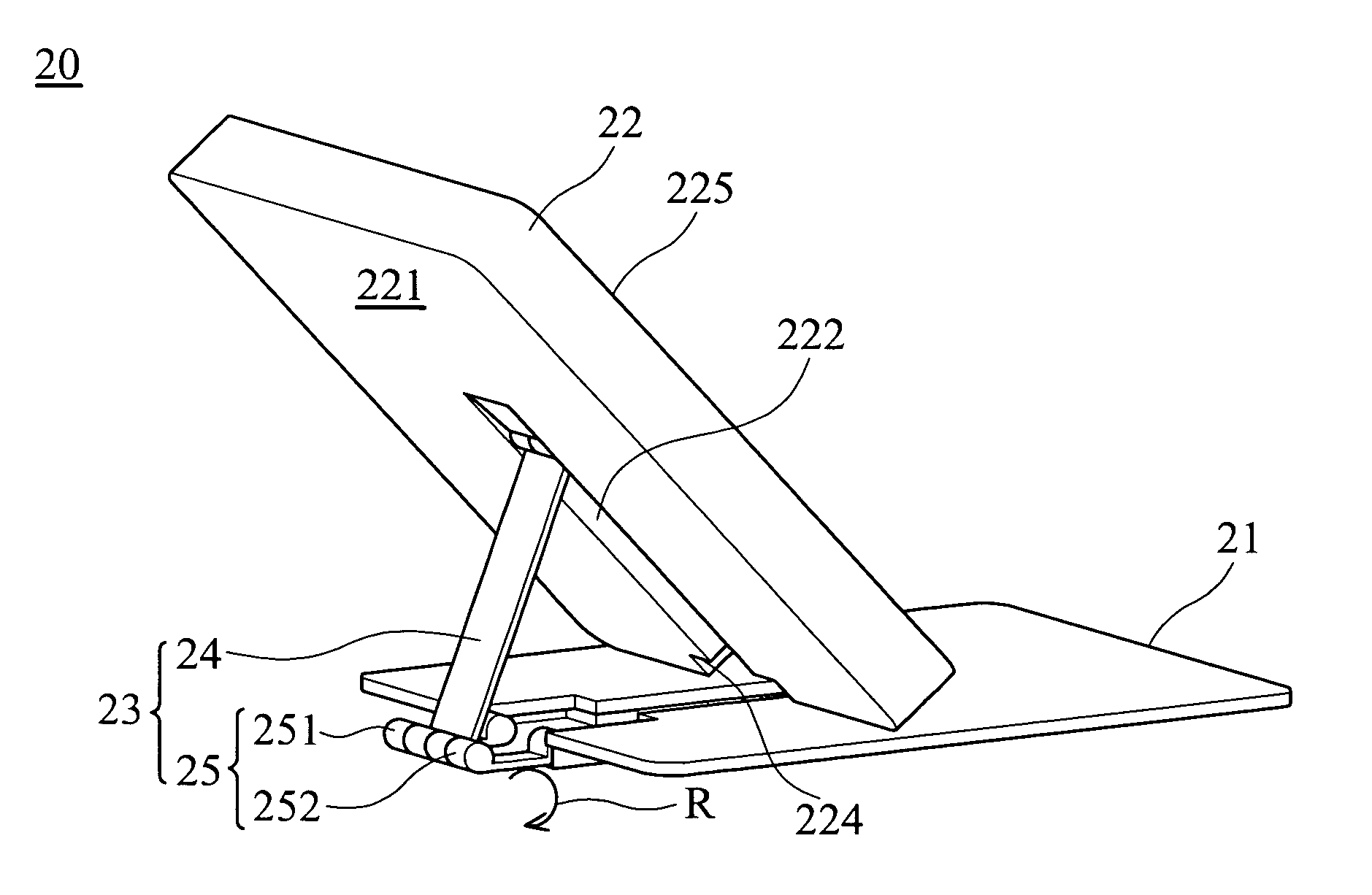
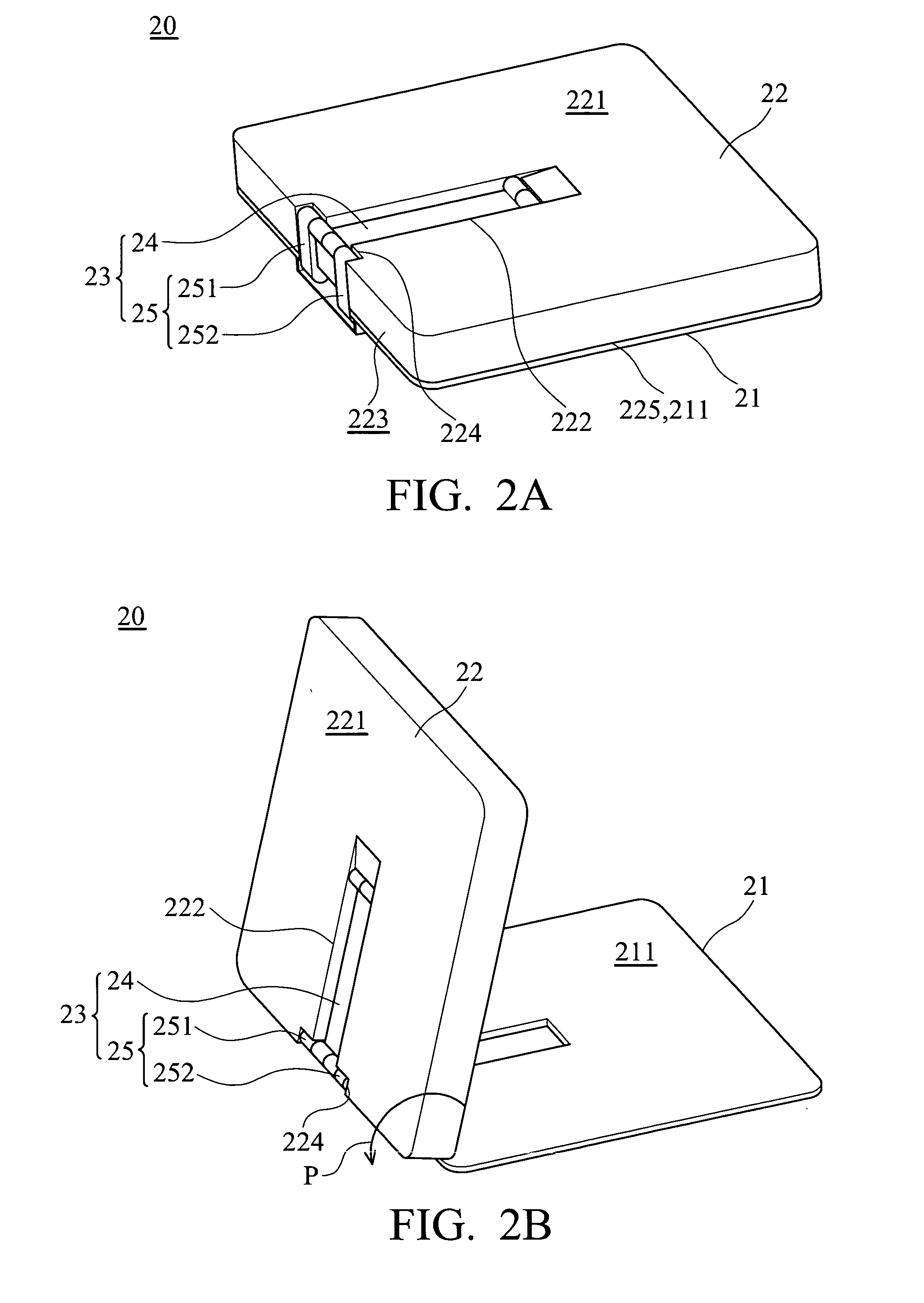
[0012]Referring to FIGS. 2A and 2F, the portable electronic device 20 of the invention comprises a base 21, a cover 22 and a linkage mechanism 23. The base 21 comprises a third surface 211. The linkage mechanism 23 comprises a first linkage assembly 24 and a linkage assembly 25. The first linkage assembly 24 is pivoted to the cover 22. The cover 22 comprises a first surface 221, a second surface 223 and a display surface 225. The first surface 221 is located on the back surface of the cover 22. The first surface 221 and the second surface 223 respectively comprises a first space 222 to accommodate the first linkage assembly 24 and a second space 224 to accommodate the ...


PUM


Abstract

A portable electronic device comprises a base, a cover and a linkage mechanism. The linkage mechanism comprises a first linkage assembly and a second linkage assembly. The first linkage assembly pivots to the cover. The second linkage assembly pivots to the first linkage assembly and the base, respectively. The second linkage assembly is movably installed on the base.

Description

BACKGROUND OF THE INVENTION[0001]1. Field of the Invention[0002]The invention relates to a portable electronic device, and in particular to a portable electronic device having a cover.[0003]2. Description of the Related Art[0004]Recently, common portable electronic devices are personal digital assistants (PDAs) and cell phones. Referring to FIG. 1, a conventional portable electronic device 10 comprises a base 11, a cover 12 and a connecting mechanism 13. The cover 12 is pivoted to the base 11 via the connecting element 13. The cover 12 is opened to reveal a display 121 before using the portable electronic device 10. When a user opens the cover 12, the volume of the portable electronic device 10 increases. Thus, controlling the portable electronic device 10 when in a user's palm is not convenient.BRIEF SUMMARY OF INVENTION[0005]A detailed description is given in the following embodiments with reference to the accompanying drawings. The invention provides a portable electronic device....

Claims


Application Information

Patent Timeline
IPC IPC(8): G06F1/16
CPCG06F1/1626G06F2200/1634G06F1/1681G06F1/166
Inventor CHUANG, I-CHENGHO, SAN-CHIWANG, KO-MIN
Owner HTC CORP
Features
  • Generate Ideas
  • Intellectual Property
  • Life Sciences
  • Materials
  • Tech Scout
  • Unparalleled Data Quality
  • Higher Quality Content
  • 60% Fewer Hallucinations
Learn More