Terminal location system and positioning method

a terminal and location system technology, applied in the field of wireless communication systems, can solve the problems of increasing the complexity of the process of disposing the base stations so that the system becomes capable of locating the terminal, and the increase of the cost of installation and maintenance. the effect of simplifying the introduction of the terminal location system

Inactive Publication Date: 2007-09-20
HITACHI LTD
View PDF11 Cites 143 Cited by
  • Summary
  • Abstract
  • Description
  • Claims
  • Application Information

AI Technical Summary

Benefits of technology

[0016]According to the one embodiment of this invention, since it is not necessary to measure disposed positions manually and the relative coordinates of the base stations can be found by wireless communication, introduction of the terminal location system can be simplified.

Problems solved by technology

In constructing a location system of a terminal using a plurality of base stations described above, there is a problem that a procedure of disposing the base stations so that the system becomes capable of locating the terminal is complex.
However, the conventional terminal location system poses a problem that since the coordinates of the base stations are measured manually, manpower, time, and cost in initially introducing the system and in maintenance are large, which forms a barrier against introduction of the system.
Because of these constraints, a cost at the time of introduction of the system and a cost at the time of maintenance increase.
Moreover, there is also a problem of decrease of flexibility in base station disposition.
Furthermore, when adding a new base station to expand a possible area of the terminal location, there will arise a problem of increase in manpower, time, and costs similarly.

Method used


Image

  • Terminal location system and positioning method
  • Terminal location system and positioning method
  • Terminal location system and positioning method

Examples


first embodiment

[0034]A first embodiment of receiving equipment of this invention will be described using FIGS. 1A to 10.

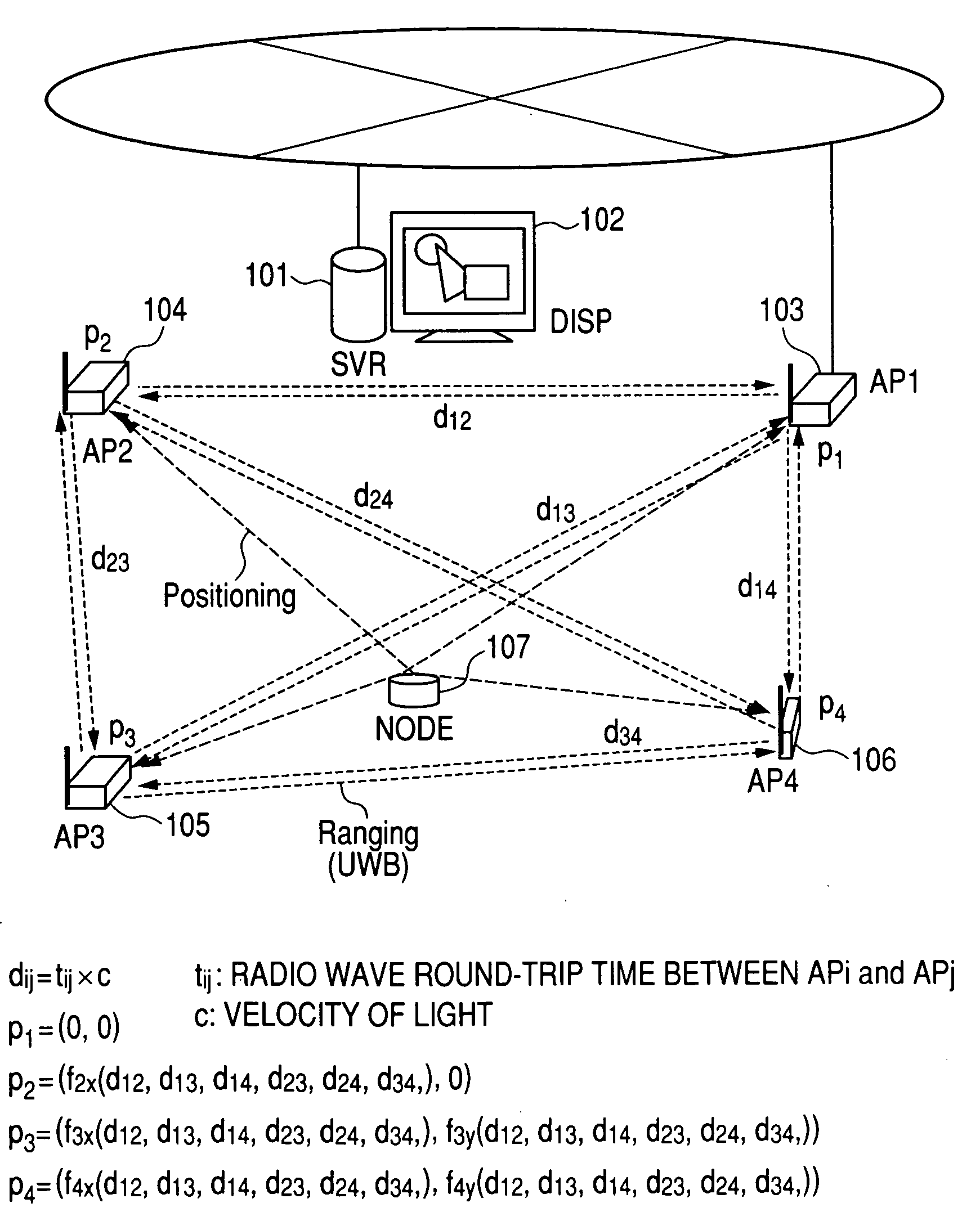
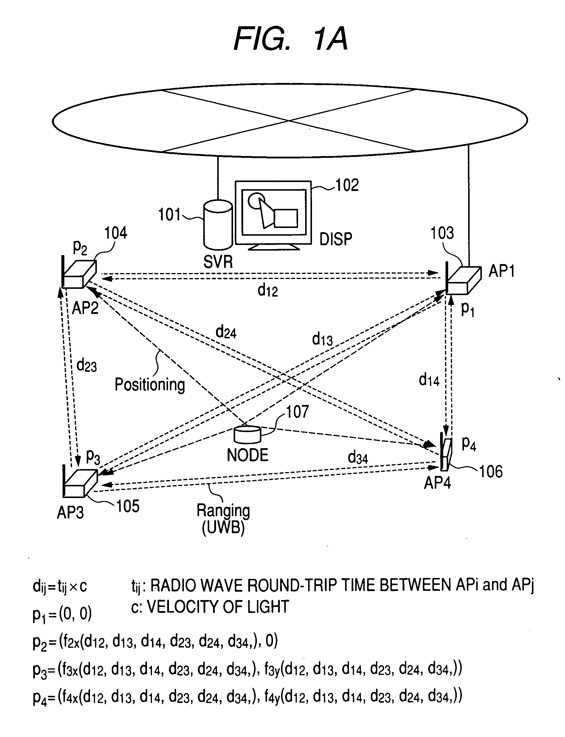
[0035]FIG. 1A is a configuration diagram of a terminal location system of the first embodiment.

[0036]The terminal location system of the first embodiment has a location server (SVR) 101, a display (DISP) 102, base stations (AP1 to AP4) 103, 104, 105, and 106, and a terminal (NODE) 107.

[0037]The location server 101 is a computer for calculating a position of the terminal 107 connected with the terminal location system of this embodiment, being equipped with a CPU, a storage device, and a communication interface. An input / output device 102 is a user interface connected with the location server 101, including a keyboard, a mouse, and a display unit, for example.

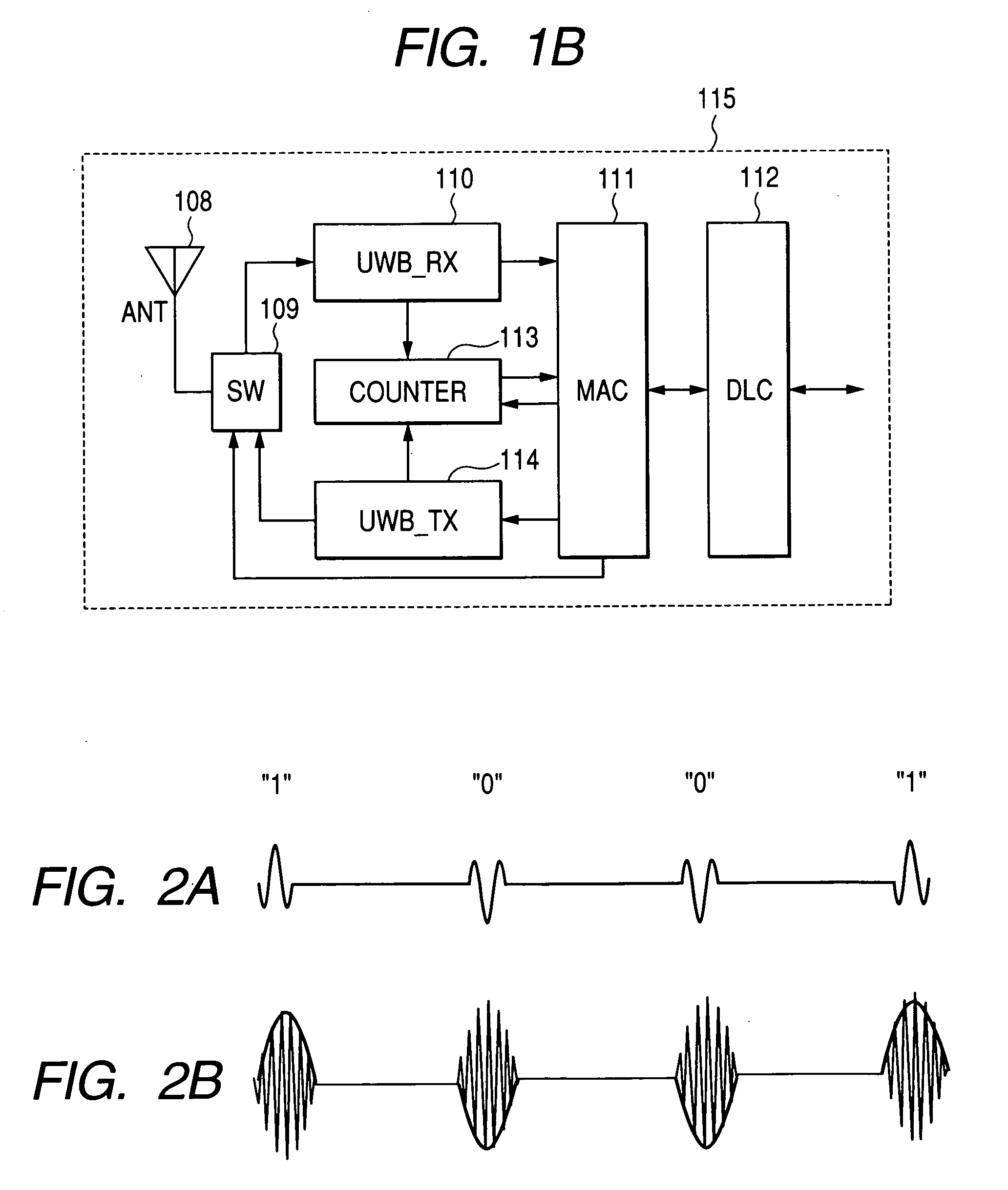
[0038]The base stations (AP1 to AP4) 103, 104, 105, and 106 are each equipped with a wireless communication apparatus 115 for measuring transmission / reception timing of a radio signal. At least one base station (in this embod...

second embodiment

[0142]Next, a second embodiment of this invention will be described.

[0143]FIG. 11 is a block diagram of a terminal location system of the second embodiment of this invention.

[0144]In contrast to the first embodiment where the location server 101 is connected with the base station (AP1) 103 by wire, in the second embodiment that will be explained below, base stations (AP1 to AP4) 1403-1406 are connected with a location server 1401 by radio. That is, instead of wire communication between the location server 101 and the base station (AP1) 103 explained in the first embodiment, the base stations (AP1 to AP4) 1403-1406 each perform wireless communication directly with the location server 1401 in the second embodiment.

[0145]Although the location system is so configured that a high-order wireless communication system among these base stations (AP1 to AP4) 1403-1406 and the location server 1401 is wireless LAN and a low-order wireless communication system among the base stations (AP1 to AP4...

third embodiment

[0154]Next, a third embodiment of this invention will be described.

[0155]FIG. 12 is a block diagram of a terminal location system of the third embodiment according to this invention.

[0156]A terminal location system of the third embodiment has a location server (SVR) 1501, a display (DISP) 1502, base stations (AP1 to AP6) 1503, 1504, 1505, 1506, 1507, and 1508, and a terminal (NODE) 1509. In the third embodiment, the same terminal location system as that of the first embodiment is constructed with the base station (AP2) 1504, the base station (AP3) 1505, the base station (AP5) 1507, and the base station (AP6) 1508. That is, since the base stations are disposed in a range exceeding a communication range of the base station, the range where positioning of the terminal is possible is expanded over the range of the first embodiment.

[0157]The base stations (AP1 to AP6) 1503-1508 of the third embodiment each have the same configuration as that of the base stations (AP1 to AP4). Moreover, t...


PUM


Abstract

A location system of a configuration that facilitates initial introduction, maintenance, and system expansion. A terminal location system basically has at least (N+1) base station (here, N=1 to 3) and a location server and finds a position of a terminal performing wireless communication in N-dimensional coordinates. Further, the terminal location system calculates distances among the at least (N+1) base stations, finds relative coordinates of the base stations, evaluates the obtained relative coordinates, determines switching to terminal location processing of finding the position of the terminal, and finds the position of the terminal using propagation times of radio signals transmitted/received among the terminal and the base stations and the obtained relative coordinates of the base stations.

Description

CLAIM OF PRIORITY[0001]The present application claims priority from Japanese application JP 2006-074616 filed on Mar. 17, 2006, the content of which is hereby incorporated by reference into this application.FIELD OF THE INVENTION[0002]This invention relates to a wireless communication system, and, more specifically, to a terminal location system for positioning a wireless communication terminal and for fixing a position of a base station used for positioning.BACKGROUND OF THE INVENTION[0003]To measure a position of a mobile terminal, a system has been proposed that calculates a propagation distance of a signal from a node to each base station and detects a position of the node by calculating differences in the time at which the plurality of base stations receive a signal transmitted from the terminal and multiplying the received time differences of arrival by the velocity of light (for example, see A. Ogino et al., “Wireless LAN integrated access system (1) Study on location system,...

Claims


Application Information

Patent Timeline
Patent Type & Authority Applications(United States)
IPC IPC(8): H04Q7/24H04W64/00H04W88/08
CPCG01S5/0205G01S5/0221G01S5/0226H04W88/08G01S5/14H04W64/00G01S5/0289G01S5/0244G01S5/02216
Inventor FUJIWARA, RYOSUKEMIYAZAKI, MASAYUKIMIZUGAKI, KENICHI
Owner HITACHI LTD
Why Eureka
Try Eureka