Method for minimizing ammonia slip from scr catalysts

a technology of ammonia slip and catalyst, which is applied in the direction of machines/engines, mechanical equipment, exhaust treatment electric control, etc., can solve the problems of difficult control of the generation rate or dosage of appropriate ammonia levels, no system, and task becoming a challenge, so as to reduce nox emissions, reduce nox level, and increase engine-out nox level

Inactive Publication Date: 2013-01-03
FORD GLOBAL TECH LLC
View PDF7 Cites 21 Cited by
  • Summary
  • Abstract
  • Description
  • Claims
  • Application Information

AI Technical Summary

Benefits of technology

[0013]It should be understood that the summary above is provided to introduce in simplified form a selection of concepts that are further described in the detailed description. It is not meant to identify key or essential features of the claimed subject matter, the scope of which is defined uniquely by the claims that follow the detailed description. Furthermore, the claimed subject matter is not limited to implementations that solve any disadvantages noted above or in any part of this disclosure.

Problems solved by technology

No matter which of the before mentioned methods is applied to provide ammonia in a particular exhaust gas aftertreatment device, it is difficult to control the generation rate or dosage of appropriate ammonia levels, in particular during different operating conditions of the engine.
In other words, it makes no sense to provide a system to reduce NOx which on the other hand expels a different type of emissions.
This task is becoming a challenge, because NOx selective reduction catalysts (SCR) are good adsorbents for ammonia, and unreacted ammonia could slip out of the catalyst during operation.
Consequently, this additional catalyst makes the aftertreatment device even more expensive and should therefore be avoided.
To summarize, in spite of a great number of methods dealing with control of reductant injection and avoiding the leak of the reductant to the environment, there is still the problem to control ammonia slip, especially at transient conditions, when a rapid increase of exhaust gas flow rate and temperature occurs.

Method used


Image

  • Method for minimizing ammonia slip from scr catalysts
  • Method for minimizing ammonia slip from scr catalysts
  • Method for minimizing ammonia slip from scr catalysts

Examples


Embodiment Construction

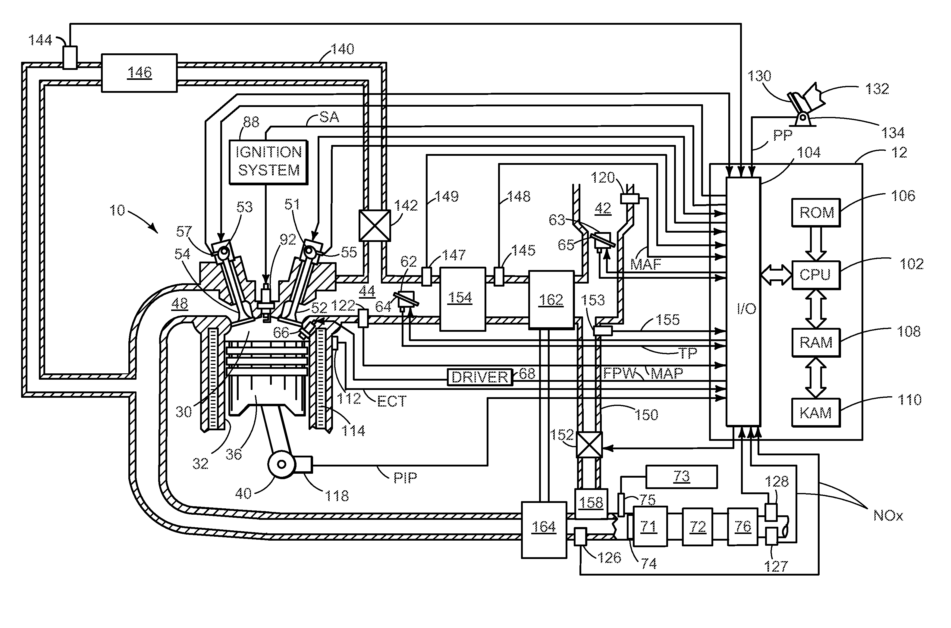
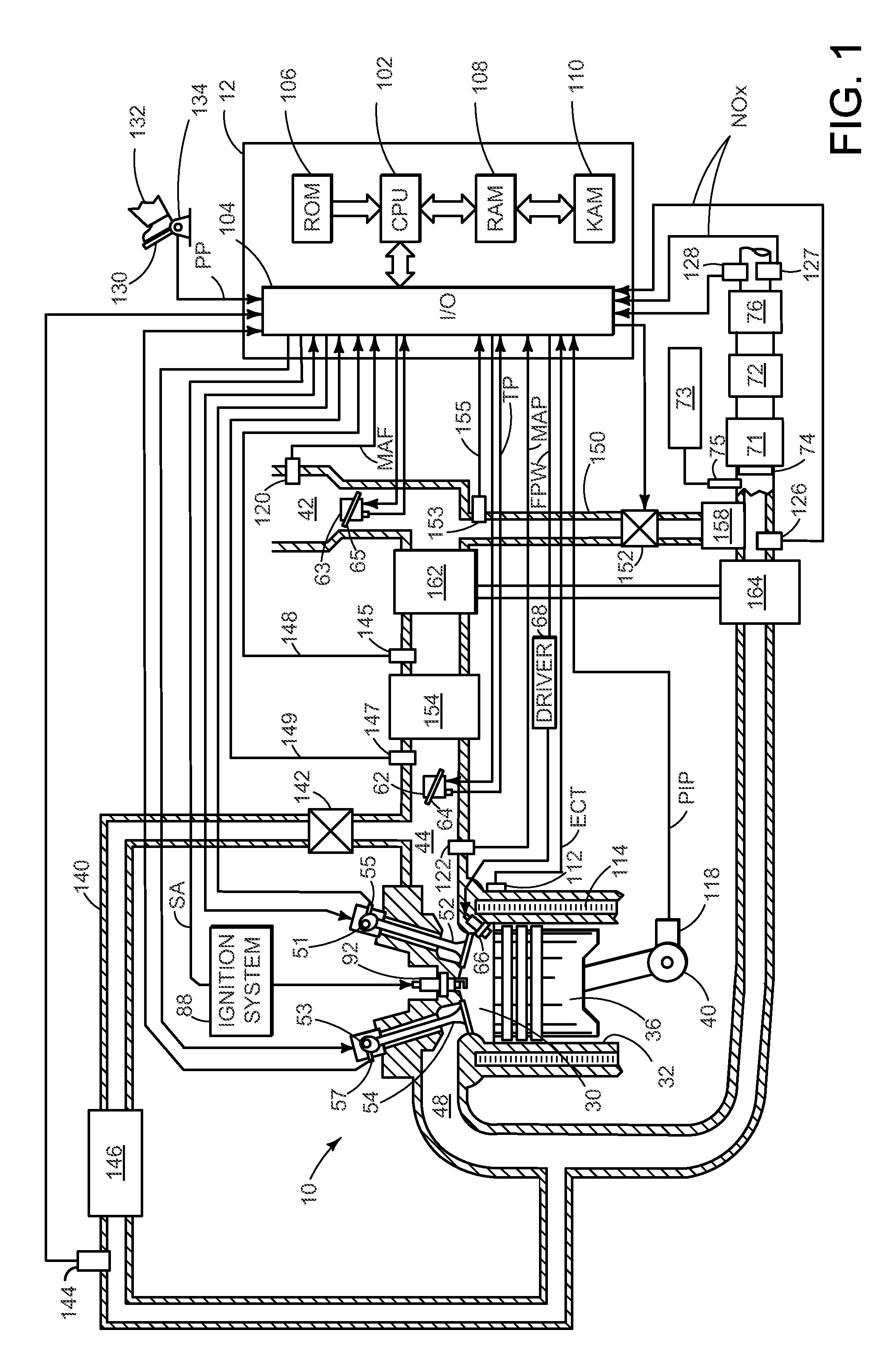
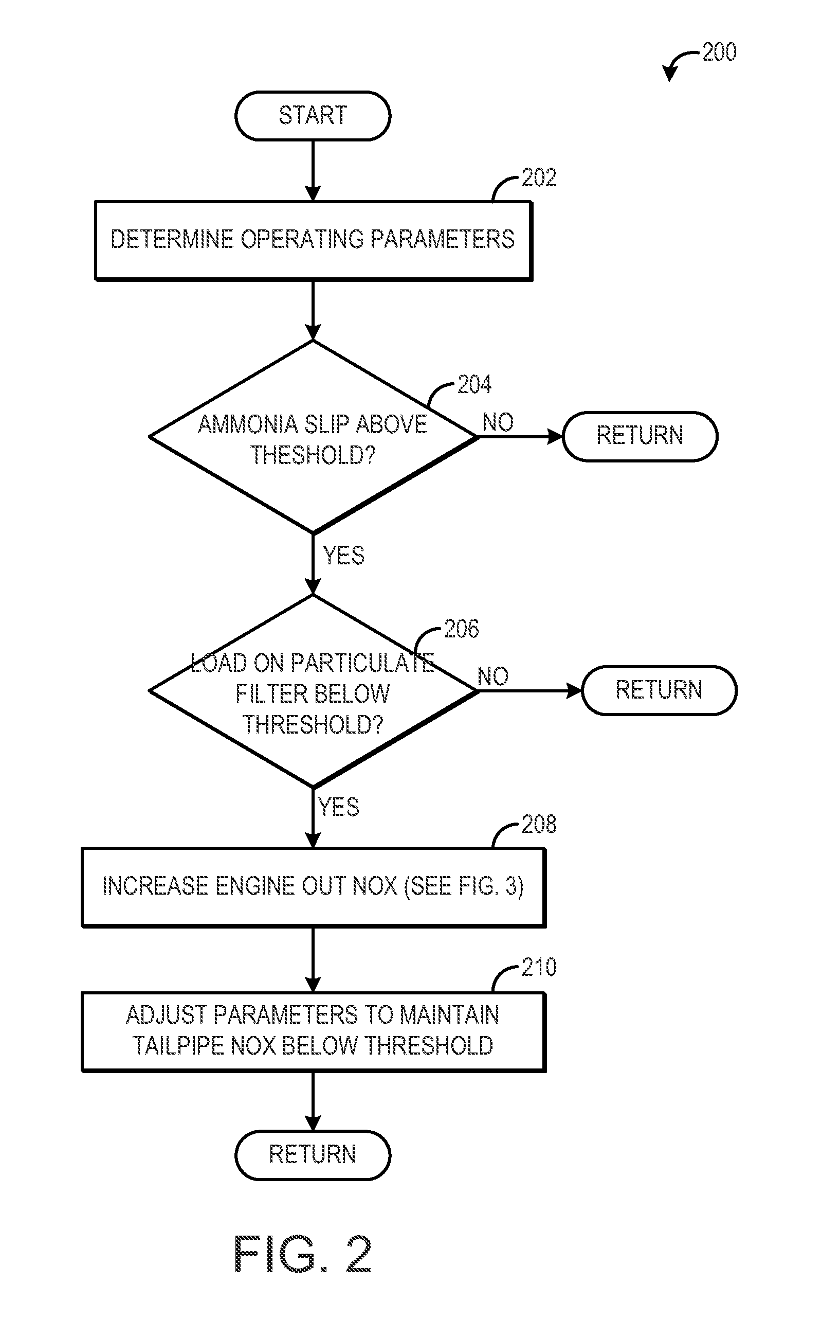
[0019]In engine systems that operate with relatively lean combustion, such as diesel engines, high levels of NOx are produced. To control these NOx emissions, the engine system may include a selective catalyst reduction (SCR) device configured to convert NOx utilizing an injected reductant such as ammonia or urea. While SCR devices are effective at reducing NOx emissions, under some conditions, excess ammonia may be released from the devices. To control this ammonia slip, engine-out NOx levels may be increased by reducing an EGR amount, for example. The excess NOx present in the exhaust at the SCR device may react with the excess ammonia, reducing the amount of ammonia slip. The increase in engine NOx emissions may be controlled such that tailpipe NOx emissions downstream of the SCR device do not increase above a desired threshold.

[0020]The idea behind this disclosure is that it has been found that the occurrence of ammonia slip can be considered as a lack of NOx in the exhaust gas;...


PUM


Abstract

Embodiments for reducing ammonia slip are provided. In one example, a method for reduction of ammonia emissions from an engine exhaust gas aftertreatment device with an SCR catalyst comprises determining a concentration of NOx and / or ammonia in the exhaust gas aftertreatment device, comparing a determined value of NOx and / or ammonia concentration with a nominal value for ammonia and NOx, respectively, and if an actual or shortly forecasted ammonia concentration is above the respective nominal value, triggering engine conditions with higher exhaust NOx concentration. In this way, ammonia slip may be reduced without degrading fuel economy.

Description

RELATED APPLICATIONS[0001]The present application claims priority to European Patent Application Number 11172069.4, filed on Jun. 30, 2011, the entire contents of which are hereby incorporated by reference for all purposes.FIELD[0002]The current disclosure is related to a method and system for reduction of ammonia emissions from a combustion engine exhaust gas aftertreatment device with an SCR catalyst.BACKGROUND AND SUMMARY[0003]In recent times, internal combustion engine aftertreatment devices have been provided with catalytic systems to reduce NOx, which base on the recombination reaction of NOx with ammonia to nitrogen and water on the SCR (Selective Catalytic Reduction) catalyst. The required ammonia is typically provided by an external source, like AdBlue®, which is a water-based solution of urea. Alternatively, ammonia could be in situ synthesized by a special catalyst from the NOx in exhaust gas. No matter which of the before mentioned methods is applied to provide ammonia i...

Claims


Application Information

Patent Timeline
Patent Type & Authority Applications(United States)
IPC IPC(8): F01N3/20F02B47/08F02M25/07F01N11/00F01N3/24
CPCF01N3/208F01N2560/021Y02T10/24F01N2900/1616F01N2610/02Y02T10/12
Inventor DUBKOV, ALEXEY A.BALENOVIC, MARIOHARMSEN, JANUKROPEC, ROBERTCARBERRY, BRENDAN PATRICK
Owner FORD GLOBAL TECH LLC
Why Eureka
Try Eureka