Method for replacing 3D objects in 2d environment

a technology of 2d environment and object replacement, applied in the field of 2d environment object replacement method, can solve the problem of difficult to precisely replace an object in the 2d environmen

Active Publication Date: 2015-11-19
WEST TEXAS TECH PARTNERS LLC
View PDF12 Cites 23 Cited by
  • Summary
  • Abstract
  • Description
  • Claims
  • Application Information

AI Technical Summary

Benefits of technology

[0006]It should be understood that the summary above is provided to introduce in simplified form a selection of concepts that are further described in the detailed description. It is not meant to identify key or essential features of the claimed subject matter, the scope of which is defined uniquely by the claims that follow the detailed description. Furthermore, the claimed subject matter is not limited to implementations that solve any disadvantages noted above or in any part of this disclosure.

Problems solved by technology

Namely, although objects may be positioned independently within the 2D environment, it may be difficult to precisely replace an object in the 2D environment.

Method used


Image

  • Method for replacing 3D objects in 2d environment
  • Method for replacing 3D objects in 2d environment
  • Method for replacing 3D objects in 2d environment

Examples


Embodiment Construction

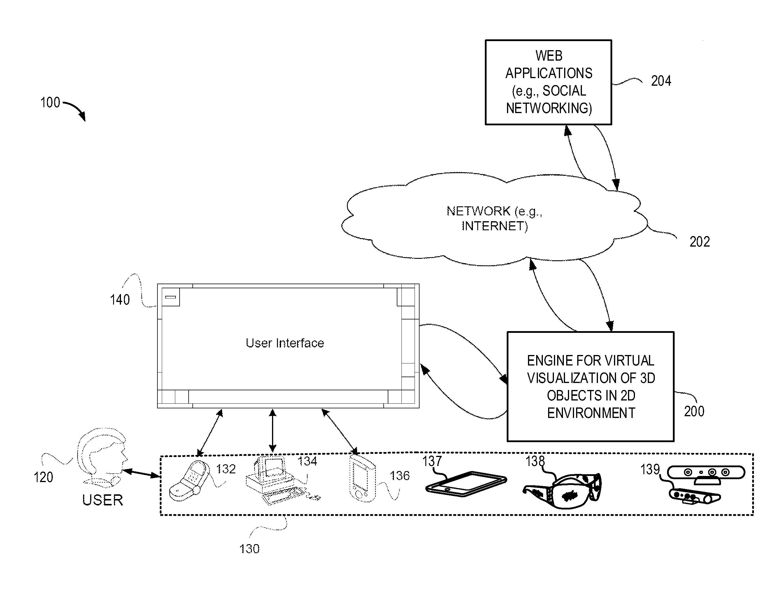
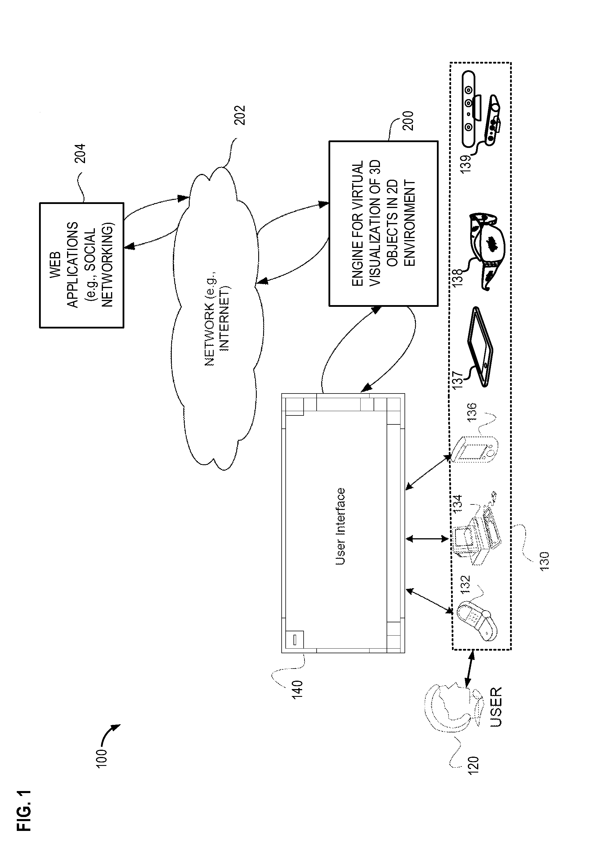
[0015]The present description relates to visualization and adding of 3D models of objects to a 2D environment, wherein the 2D environment is a real environment represented by a photo or video and other graphical representations. A user may import photographic images, digital images, video images, and other graphical representations of the 2D environment. Further, the 2D environment may include existing graphical materials or graphical materials captured as a still image or a live feed image. The 2D environment may serve as the background environment for adding a 3D model of an object.

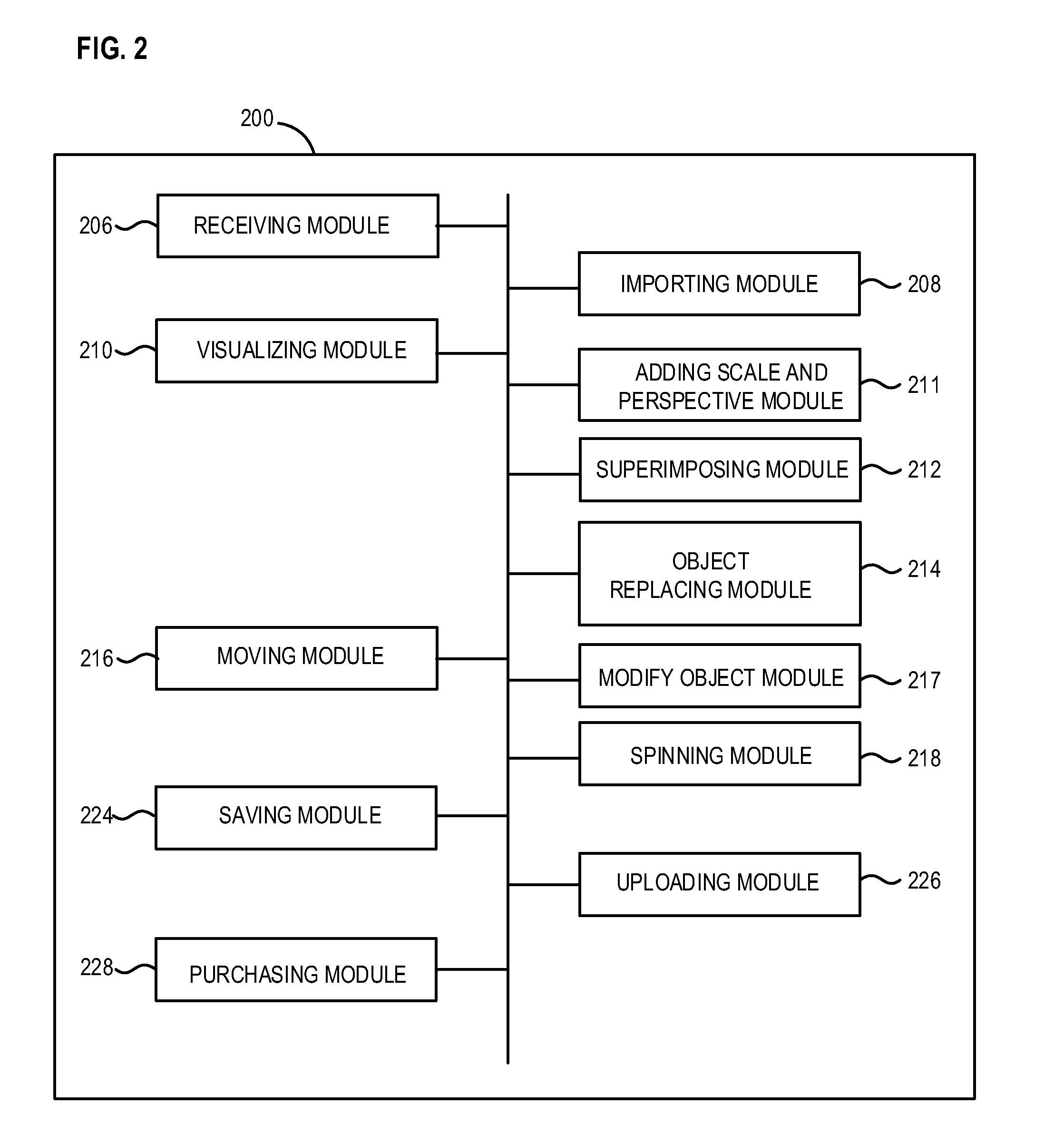
[0016]The 3D object is associated with a set of data which includes a defined set of parameters relevant to the 3D object. The parameters may include attributes, instructions, and other such scripts associated with and essential for graphical use of the 3D object. Characteristics of the 3D object, interaction between object entities may be analyzed with such associated data. The set of data associated w...


PUM


Abstract

Example systems and methods for virtual visualization of a three-dimensional (3D) model of an object in a two-dimensional (2D) environment. The method may include superimposing a first 3D model of an object onto the 2D environment, and replacing the first 3D model of the object with a second 3D model of an object. Further, the method may include superimposing a smart 3D model of an object onto the 2D environment. Additionally, the method may include a code or mark to identify images of the 2D environment to which 3D models of objects have been superimposed.

Description

CROSS-REFERENCE TO RELATED APPLICATIONS[0001]The present application claims priority to U.S. Provisional Patent Application No. 61 / 992,759 entitled “METHOD FOR FORMING WALLS TO ALIGN 3D OBJECTS IN 2D ENVIRONMENT”, filed on May 13, 2014, the entire contents of which are hereby incorporated by reference for all purposes. The present application also claims priority to U.S. Provisional Patent Application No. 61 / 992,629 entitled “METHOD FOR PROVIDING SCALE TO ALIGN 3D OBJECTS IN 2D ENVIRONMENT”, filed on May 13, 2014, the entire contents of which are hereby incorporated by reference for all purposes. The present application claims further priority to U.S. Provisional Patent Application No. 61 / 992,719 entitled “METHOD FOR PROVIDING A PROJECTION TO ALIGN 3D OBJECTS IN 2D ENVIRONMENT”, filed May 13, 2014, the entire contents of which are hereby incorporated by reference for all purposes. The present application claims further priority to U.S. Provisional Patent Application No. 61 / 992,774 e...

Claims


Application Information

Patent Timeline
Patent Type & Authority Applications(United States)
IPC IPC(8): G06T19/00G06T15/20G06T19/20G06T13/20
CPCG06T19/006G06T13/205G06T15/20G06T19/20G06T2215/12G06T2215/16G06T2219/2024G06T2219/012G06T2219/2004G06T2219/2008G06T2219/2012G06T2219/2016G06T2219/008G06F30/13G06F30/00G06F3/04815G06F3/04845G06F3/0486G06F3/0488G06F2203/04802G06T15/10G06T2219/004
Inventor JOVANOVIC, MILOS
Owner WEST TEXAS TECH PARTNERS LLC
Why Eureka
Try Eureka