Brake holder for a floating-caliper disk brake with a brake pad guide spring

a disc brake and brake pad technology, applied in the direction of axially engaging brakes, slack adjusters, brake elements, etc., can solve the problems of principally rattle-free guiding of the brake pads, poor or complicated mountability of the slide spring element on the brake holder, etc., and achieve the effect of convenient mounting

Inactive Publication Date: 2006-04-06
CONTINENTAL TEVES AG & CO OHG
View PDF10 Cites 22 Cited by
  • Summary
  • Abstract
  • Description
  • Claims
  • Application Information

AI Technical Summary

Benefits of technology

[0004] This object is achieved by a brake holder of a floating-caliper disc brake for motor vehicles comprising a corresponding brake pad guide spring. The brake holder comprises axially extending holder arms at which associated brake pads are displaceably arranged, said brake pads being arranged on either side of a brake disc and mountable in the brake holder in a radial direction. For ease of displaceability of the brake pads in the brake holder, at least one brake pad guide spring is provided, which is arranged between the brake holder and the brake pads. In a novel manner, the brake pad guide spring is mountable on the brake holder in a generally radial direction and locked at the brake holder in both radial and axial directions by means of at least one fixing clamp. To this end, the brake pad guide spring is simply shifted into a corresponding portion of the brake holder which is simultaneously provided for the displaceable brake pad guide, with at least one fixing clamp becoming locked at the brake holder. The locking engagement by means of the fixing clamp is used to fix the brake pad guide spring safely on the brake holder, although it is easy to mount. For the additionally rattle-free brake pad guide, the brake pad guide spring includes at least one spring arm that fixes at least one brake pad under spring load relative to the brake holder in a clearance-free manner.

Problems solved by technology

Such a form-fit connection of slide spring element and brake holder implies, however, a poor or complicated mountability of the slide spring element on the brake holder.
In addition, the simultaneous resilient arrangement of the brake pad by means of the slide spring element is insufficient so that a principally rattle-free guiding of the brake pads cannot be safeguarded.

Method used


Image

  • Brake holder for a floating-caliper disk brake with a brake pad guide spring
  • Brake holder for a floating-caliper disk brake with a brake pad guide spring
  • Brake holder for a floating-caliper disk brake with a brake pad guide spring

Examples


Embodiment Construction

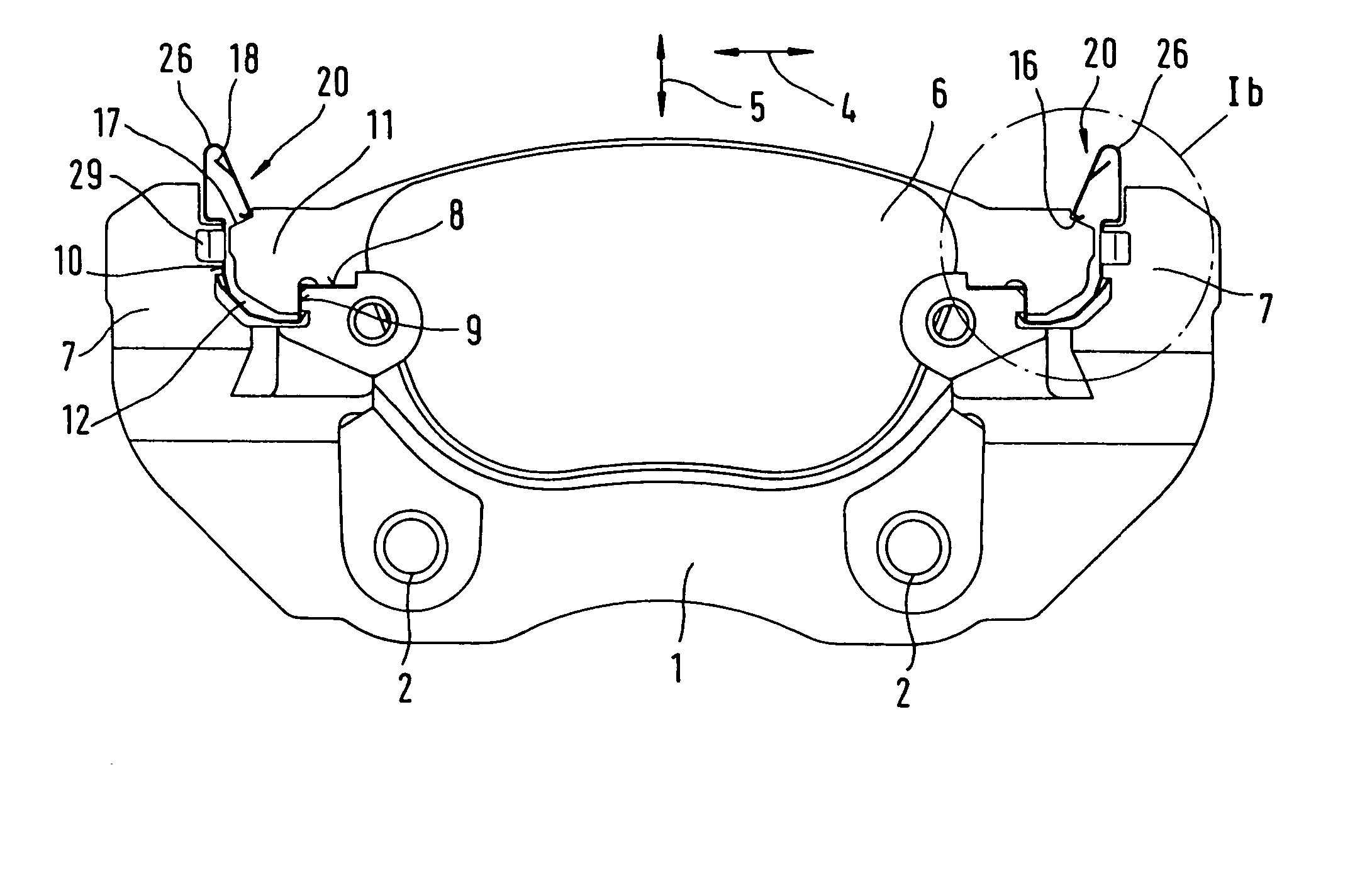
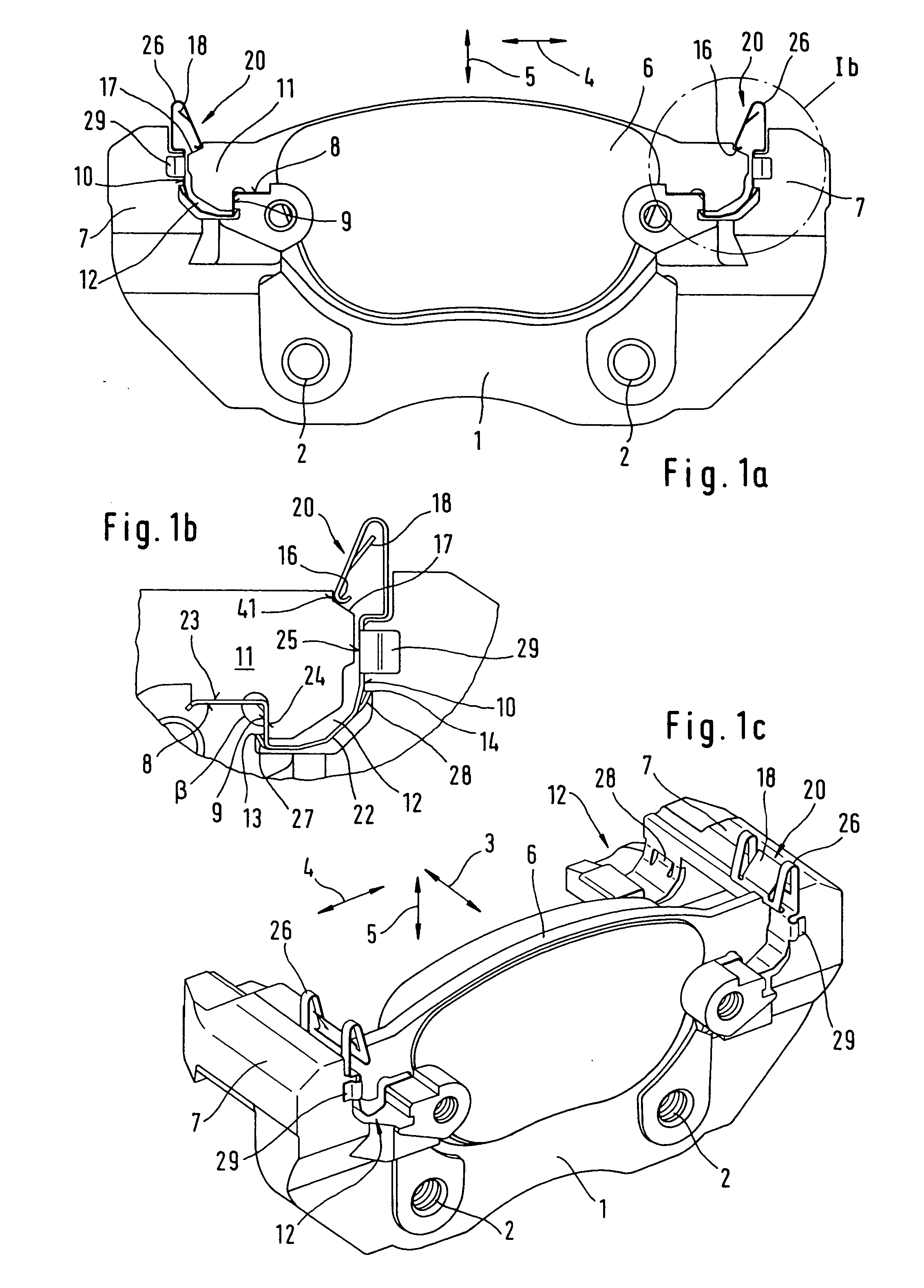
[0018] The brake holder 1 shown in the Figures is a component part of a floating-caliper disc brake frequently used in motor vehicles. Brake holder 1 is fixed to the vehicle, for example, by way of threaded bores or through-bores 2. On the other hand, it is also feasible to integrate the brake holder 1 into a component fixed to the vehicle such as the steering knuckle. The brake holder 1 is used for the slidable support of a floating caliper (not shown), on the one hand, and for an axially 3 slidable accommodation of the brake pads 6, on the other hand, said brake pads being arranged on either side of the associated brake disc. In this arrangement, the floating caliper straddles the brake disc and the brake pads 6.

[0019] To accommodate the brake pads 6, the brake holder 1 comprises holder arms 7 straddling axially 3 the radially outwards edge of the brake disc (not shown). In this respect the designations of directions used in the description of the Figures, e.g. axial 3, tangentia...


PUM


Abstract

The present invention relates to a brake holder of a floating-caliper disc brake for motor vehicles at which brake pads arranged on either side of an associated brake disc are displaceably mounted. To ensure ease of displaceability a brake pad guide spring is provided that extends between the brake holder and the brake pads. For ease of mountability of both the brake pads and the brake pad guide spring, it is arranged for that the brake pad guide spring is mountable on the brake holder in a generally radial direction and is locked at the brake holder in both radial and axial directions by means of at least one fixing clamp, and at least one spring arm is designed at the brake pad guide spring and fixes at least one brake pad under spring bias in position on the brake holder in a clearance-free manner. These provisions not only improve the mountability of a brake of this type but also the rattle-free resilient arrangement of the brake pads.

Description

TECHNICAL FIELD [0001] The present invention relates to a brake holder of a floating-caliper disc brake for motor vehicles at which brake pads arranged on either side of an associated brake disc are displaceably mounted. To ensure ease of displaceability a brake pad guide spring is provided that extends between the brake holder and the brake pads. BACKGROUND OF THE INVENTION [0002] DE 100 50 013 A1 discloses a disc brake of this type comprising a brake holder fixed to the vehicle. In this application, the brake pads are guided in the brake holder in an axially displaceable manner, and a slide spring element is placed between the brake holder and the brake pads for greater ease of displaceability, through which element at least one brake pad is locked radially at the brake holder. The sliding spring element is attached to the brake holder so as to be held captive in a radial direction. The geometrical shape of the slide spring element is adapted to a guide profile in the brake holder...

Claims


Application Information

Patent Timeline
Patent Type & Authority Applications(United States)
IPC IPC(8): F16D55/00F16D55/224F16D65/097
CPCF16D65/0972F16D65/0977F16D2055/002
Inventor HENDRICH, UWEMULLER, REINERWEILER, ROLF
Owner CONTINENTAL TEVES AG & CO OHG
Why Eureka
Try Eureka