
Police baton

a baton and police technology, applied in the field of police batons, can solve the problems of inability to reliably subdue violent suspects, inconvenient loading and reloading, and inconvenient use,

Inactive Publication Date: 2007-10-11
TUFTS BALDWIN D
View PDF23 Cites 1 Cited by
  • Summary
  • Abstract
  • Description
  • Claims
  • Application Information

AI Technical Summary

Benefits of technology

[0006] The device of the present invention can quickly and reliably restrain even the most violent suspect in a non-lethal manner without endangering nearby civilians.
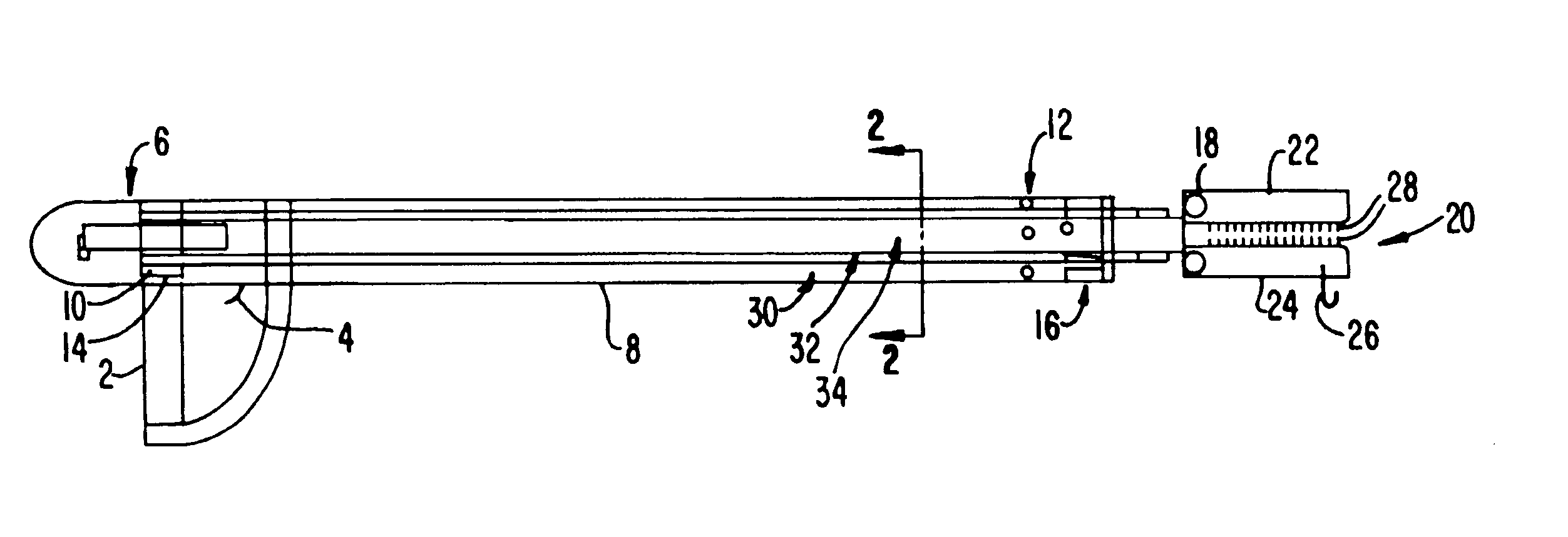
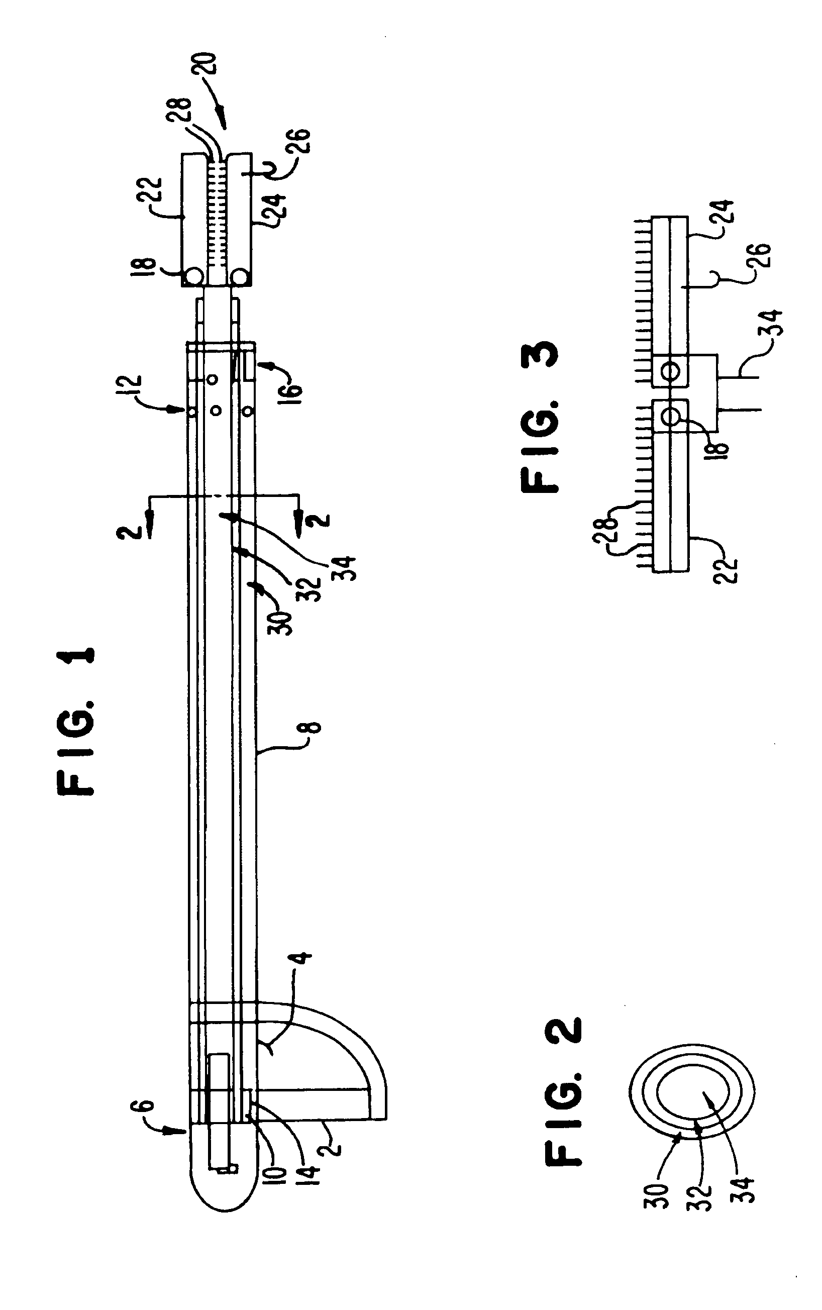
[0007] In general, the present invention is a baton-type device having a hand grip at one end, which houses an air cartridge or other device creating a thrusting force. A shaft made up of telescoping tubes connects the handgrip at one end to an end piece equipped with needles at the other end. In a preferred embodiment, the end piece comprises two parts that are folded when not in use and unfold into a flat surface for operation. Alternatively, the end piece does not fold. The tubes have spring-loaded buttons that snap and lock into position when the tubes are fully extended, preferably at an overall length of about 6 to 8 feet. The user can thus engage and restrain even the most violent suspect from a safe distance and hold that suspect indefinitely.
[0009] The extendable shaft is made up of a series of telescoping tubes that are housed within each other. The outer tube is the largest tube and is fixed to the handgrip. This outside tube houses a middle tube which is an identical oval shape so that it fits neatly within the outer tube and minimizes any rotational slippage in the clockwise or counterclockwise direction due to the oval shape. In turn, this medium tube houses an inner tube which fits neatly within the middle tube. This inner tube extends out the farthest and is connected to the end piece. It is within the scope of this invention to vary the number of tubes as the user sees fit.
[0017] In another embodiment, handcuffs are attached to the end piece so that the user can trigger the device to extend the handcuffs to a suspect without painfully engaging that person.

Problems solved by technology

The problem with the prior art is that it cannot reliably subdue a violent suspect.
The blunt knob embodiment only operates at very short distances, while the projectile embodiment takes too much time to load and reload and also endangers nearby civilians.

Method used


Image

  • Police baton
  • Police baton
  • Police baton

Examples


Embodiment Construction

[0025] Referring now to FIG. 1, the user holds the device by gripping the handgrip 2 with one hand and optionally gripping the shaft 8 with the other hand. The handgrip 2 houses an air cartridge 6 which is connected to a trigger 4. When the user pulls the trigger 4, it releases a pressurized burst from the cartridge 6, which travels through the inner tube 34 to the end piece 20. This pressure powerfully thrusts the end piece 20 outwards.

[0026] The air cartridge 6 can be fired with short or long bursts to control speed. The use of compressed-gas cartridges to deploy projectiles is well-known in the art. In another embodiment, the end piece 20 is launched out with the use of springs loaded in the back of the handgrip 2 which snap forward when triggered. In yet other embodiments explosive gasses are used to supply thrust.

[0027] Referring now to FIGS. 1 and 2, the shaft 4 is preferably comprised of a series of three telescoping oval shaped tubes 30, 32 and 34 which fit inside of each ...


PUM


Abstract

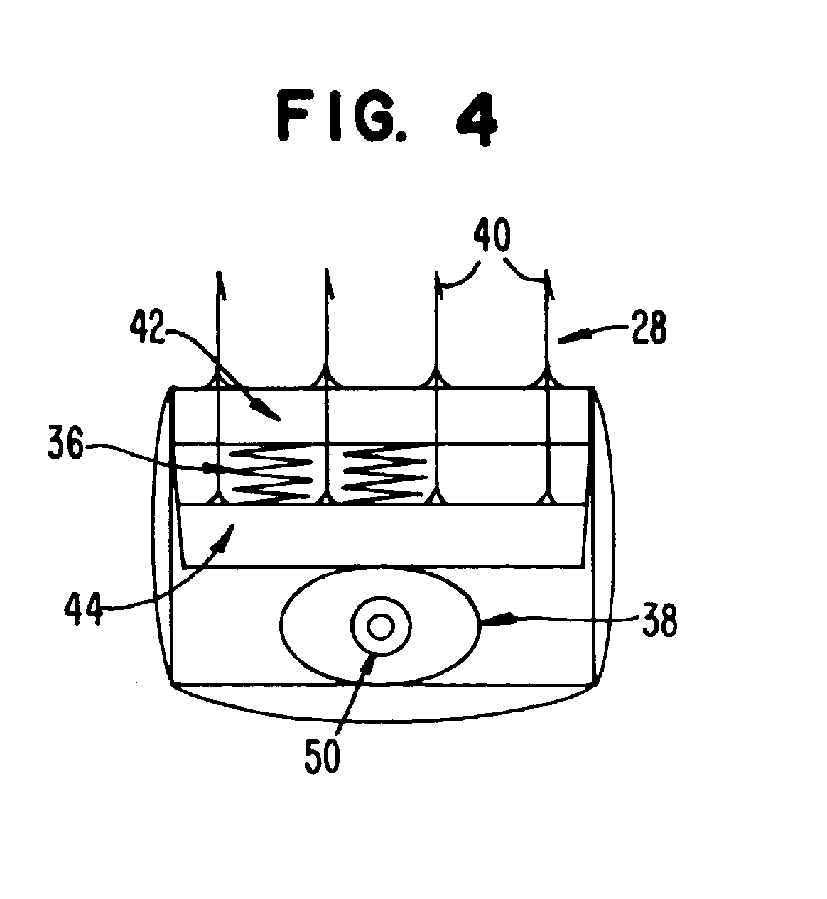
A handheld device for incapacitating dangerous suspects without endangering nearby civilians. The user holds the handgrip which has a trigger connected to a source of thrust, such as an air cartridge. When the user pulls the trigger, the air cartridge is fired and extends a shaft outwards, which has an end piece at the other end for catching suspects. The end piece unfolds into a flat surface and has needles with retractable barbs attached to the flat surface. These retractable barbs engage the suspect and incapacitate him. A cam inside of the end piece can be operated to retract the barbs and release the suspect.

Description

FIELD OF THE INVENTION [0001] The present invention relates generally to devices used to subdue suspects. More specifically, the present invention relates to a device equipped with an air cartridge and an extendable end piece that has needles attached to it for catching and incapacitating a dangerous suspect from a safe distance. BACKGROUND OF THE INVENTION [0002] Police, security personnel, and similar persons in authority often rely on non-lethal weapons to restrain dangerous individuals. These devices, including batons, stun guns, and tear gas, are powerful enough to incapacitate without actually killing. Additionally, non-lethal weapons are the best way to subdue violent suspects without unnecessarily jeopardizing the public safety. [0003] There is presently a need for incapacitating devices that are more powerful and far-reaching than the simple stick-type baton that can be used to place suspects in custody without endangering nearby civilians. [0004] U.S. Pat. No. 5,529,300 to...

Claims


Application Information

Patent Timeline
Patent Type & Authority Applications(United States)
IPC IPC(8): A63B59/00A63B15/00
CPCF41B13/10F41B15/027
Inventor TUFTS, BALDWIN D.
Owner TUFTS BALDWIN D
Learn More