Plug connector with latching mechanism

a technology of latching mechanism and plug connector, which is applied in the direction of connection, electrical apparatus, coupling device connection, etc., can solve the problem of hard to be actuated of the member

Active Publication Date: 2007-10-18
HON HAI PRECISION IND CO LTD
View PDF12 Cites 147 Cited by
  • Summary
  • Abstract
  • Description
  • Claims
  • Application Information

AI Technical Summary

Benefits of technology

[0007] Accordingly, an object of the present invention is to provide a plug connector with latch mechanism for achieving perfect signal transmission effect.

Problems solved by technology

When formed in 1990, the original goals were limited to define de facto mechanical envelopes within disk drives can be developed to fit compact computer and other small products.
However, such elongated latch member is hard to be actuated by the actuating member, otherwise the latch member must have enough thickness or made by high-quality material having enough rigidity to achieve the goal of latching reliably and unlatching easily.

Method used


Image

  • Plug connector with latching mechanism
  • Plug connector with latching mechanism
  • Plug connector with latching mechanism

Examples


first embodiment

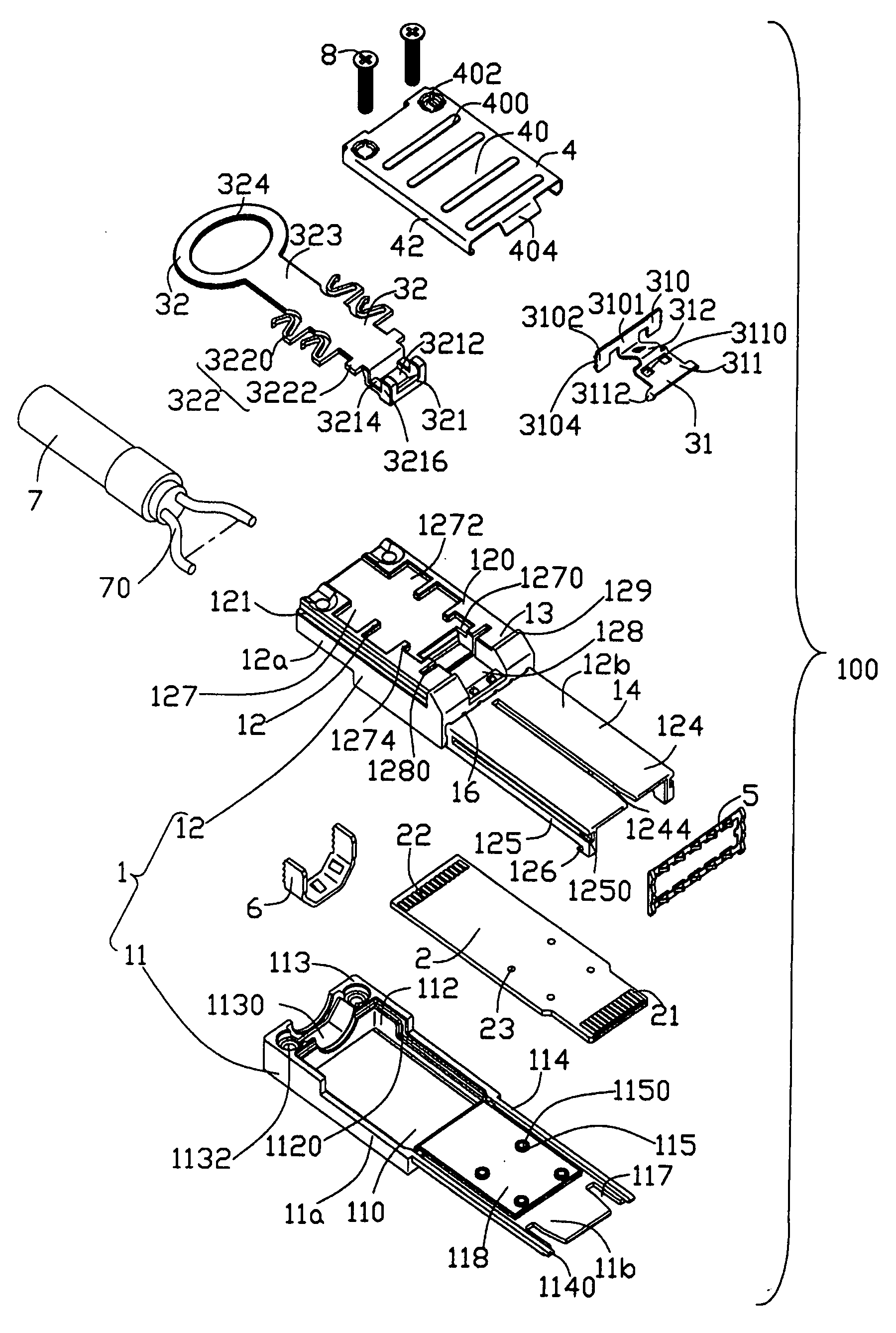
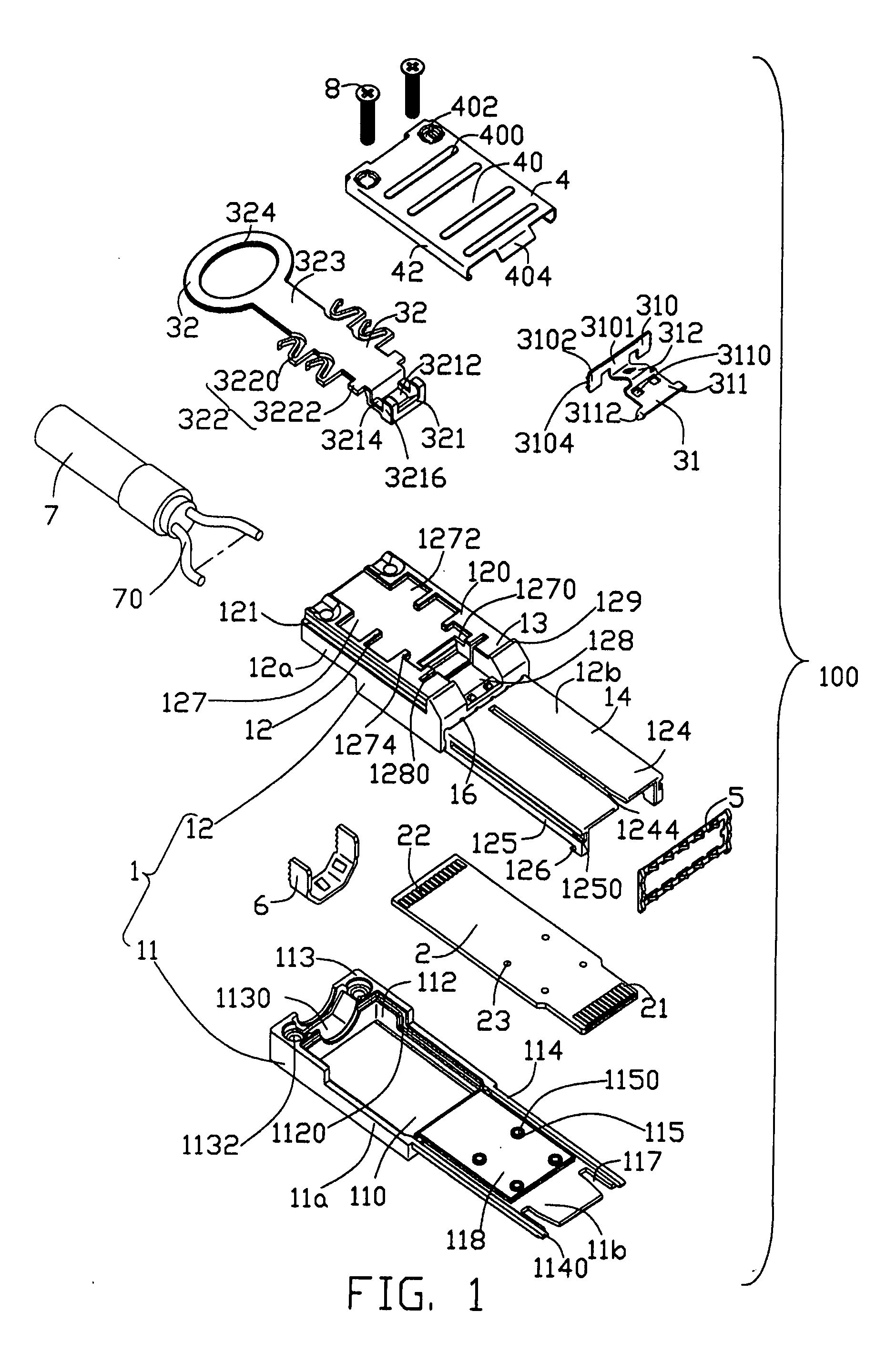
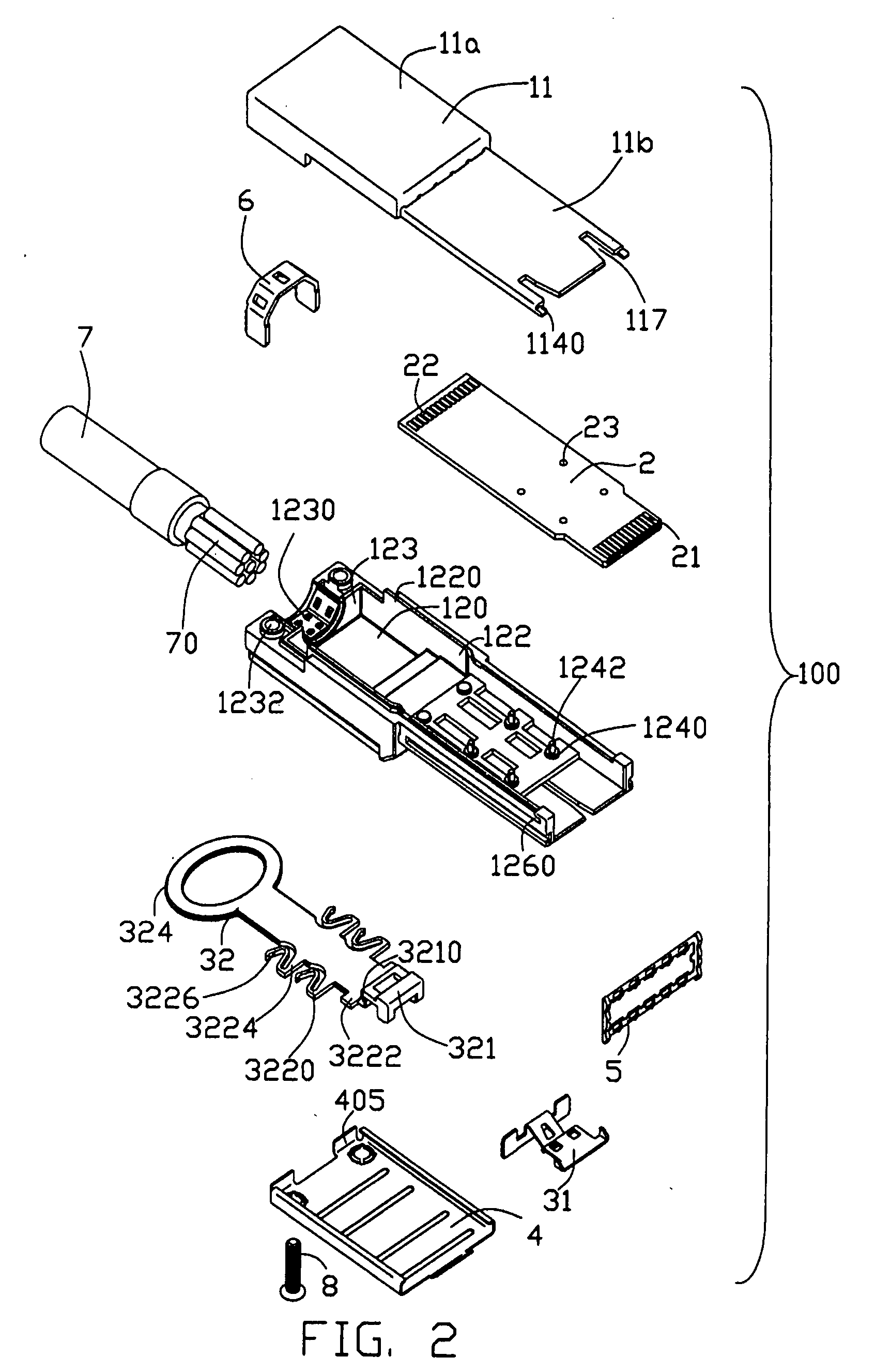
[0029] Referring to FIGS. 1-4, a plug connector 100 in accordance with the present invention comprises a housing 1, a printed circuit board (PCB) 2 located in the housing 1, a cable 7 with a cable holder 6 electrically connecting with the PCB 2, a latch mechanism 3 assembled to the housing 1, a metal shell 4 assembled to the housing 1 to partially cover the latch mechanism 3.

[0030] Please refer to FIGS. 1-8, the housing 1 of the present invention is made of metal material and comprises a base 11, a cover 12 engagble with the base 11 and a receiving space 15 formed between the base and the cover 11, 12. The metal housing 1 also comprises a rectangular base portion 13 and an elongated tongue portion 14 extending forwardly from the base portion 13.

[0031] The base 11 comprises a first base section 11a and a first tongue section 11b extending forwardly from the first base section 11a. The first base section 11a comprises a first flat portion 110, a pair of first flanges 112 and a first ...

second embodiment

[0044] A cable assembly 200 of the present invention is illustrated in FIGS. 15-18. The difference between the cable assemblies 100, 200 exists in the latch mechanisms 3, 3′. Thus, the description of the same members is omitted here and some same members are omitted in the drawing figures.

[0045] Referring to FIGS. 15-16, the latch mechanism 3′ of the cable assembly 200 has the substantially same structure as that of the latch mechanism 3 of the cable assembly 100. The latch mechanism 3′ also comprises a latch member 31′ and an actuating member 32′ cooperating with the latch member 31′. The latch member 31′ comprises a U-shape engaging portion 310′ located in a vertical surface, the flat latching portion 311 located in a horizontal surface perpendicular to the vertical surface and the inclined connecting portion 312 connecting the engaging portion 310′ with the latching portion 311. The latching portion 311 and the connecting portion 312 have the same structures as those of the latch...

third embodiment

[0049] Referring to FIGS. 19-22, a plug connector 300 in accordance with the present invention is illustrated. The latch mechanism 3″ of the plug connector 300 also comprises a latch member 31″ and an actuating member 32″ cooperating with the latch member 31″. Same members and structure description are omitted in the specification and in the drawing figures.

[0050] Referring to FIGS. 19-20, tip end of the cooperating portion 321″ of the actuating member 32″ is enlarged and forms an inclined surface 3210″ for latching with the latch member 31″.

[0051] The latch member 31″ comprises a flat connecting portion 312″ formed with a pair of rectangular holes 3120″, a latch section 311′ upwardly then flatly extending from a front edge of the connecting portion 312″, an H-shape engaging portion 310″ vertically extending from a rear edge of the connecting portion 312″, and an inclined portion 313′ upwardly and rearward extending from a middle of the engaging portion 310″. The engaging portion 3...


PUM


Abstract

A plug connector includes a housing, a latch member and an actuating member. The housing includes a base portion and a tongue portion extending forwardly from the base portion. The tongue portion has a first surface and is sized to fit within the complementary connector. The base portion has a second surface disposed at a level on the housing that is above the first surface of the tongue portion. The latch member includes an engaging portion attached to the second surface of the base portion and a latching portion extending beyond the base portion and located above the first surface of the tongue portion. The actuating member has an operating portion extending beyond said base portion, a cooperating portion disposed between the latch member and said second surface of the base portion, and an intermediate portion interconnecting the operating portion and the cooperating portion. The actuating member is sized, structured and arranged such that movement of said actuating member away and toward said tongue portion caused the latching portion of the latch member to be raised and lowered relative to the first surface of the tongue portion. The intermediate portion of the actuating member has a portion being sized, structured and arranged such that movement of the actuating member away and toward said tongue portion causing the portion of the intermediate portion to be compressed by the base portion and to provide elastic restoring force to the latching member.

Description

CROSS-REFERENCE TO RELATED APPLICATIONS [0001] This application is a CA (Continuation Application) of U.S. patent application Ser. No. 11 / 213048 filed on Aug. 26, 2005 and entitled “PLUG CONNECTOR WITH EMI GASKET”, and closely related to U.S. Pat. No. 7,134,914 and entitled “CABLE CONECTOR ASSEMBLY WITH LATCHING MECHANSIM”, both of which have the same applicant and assignee as the present invention.BACKGROUND OF THE INVENTION[0002] 1. Field of the Invention [0003] The present invention generally relates to a plug connector, and more particularly to a plug connector used for high-speed signal transmission. [0004] 2. Description of Related Art [0005] A committee called SFF is an ad hoc group formed to address storage industry needs in a prompt manner. When formed in 1990, the original goals were limited to define de facto mechanical envelopes within disk drives can be developed to fit compact computer and other small products. Specification SFF-8088 defines matable Compact Multilane S...

Claims


Application Information

Patent Timeline
Patent Type & Authority Applications(United States)
IPC IPC(8): H01R13/627
CPCH01R13/6335H01R13/6596H01R13/6592H01R13/6584
Inventor WU, JERRY
Owner HON HAI PRECISION IND CO LTD
Why Eureka
Try Eureka