
Eureka
For R&D, Eureka makes reading and utilizing patents & technical documents easy.
Eureka AIR
Designed for self-driven R&D workflows. Generate viable solutions, solve complex R&D challenges, empower your innovation with AI.

Eureka Materials
Designed for material experts only. Revolutionize your material R&D, from search, analyze, to developing new materials.

TechResearch
Generate reliable direction feasibility study reports for your R&D in just a few steps.

TechSeek
Discover and master advanced knowledge NOW. Basics, ideas, possibilities, all at once.

TechMind
As an expert in R&D Theories, TechMind can generates customized viable solutions instantly.

TechRisk
Analyze your overall solution with one click, know your potential R&D risks in advance.

TechMonitor
Get weekly tech updates, stay abreast of the latest tech innovations and key insights.
Profile Designed for the Construction of a Floor for a Pool and Capable of Floating and Being Immersed
- Summary
- Abstract
- Description
- Claims
- Application Information
AI Technical Summary
Benefits of technology
Problems solved by technology
Method used
Image

Examples
Example
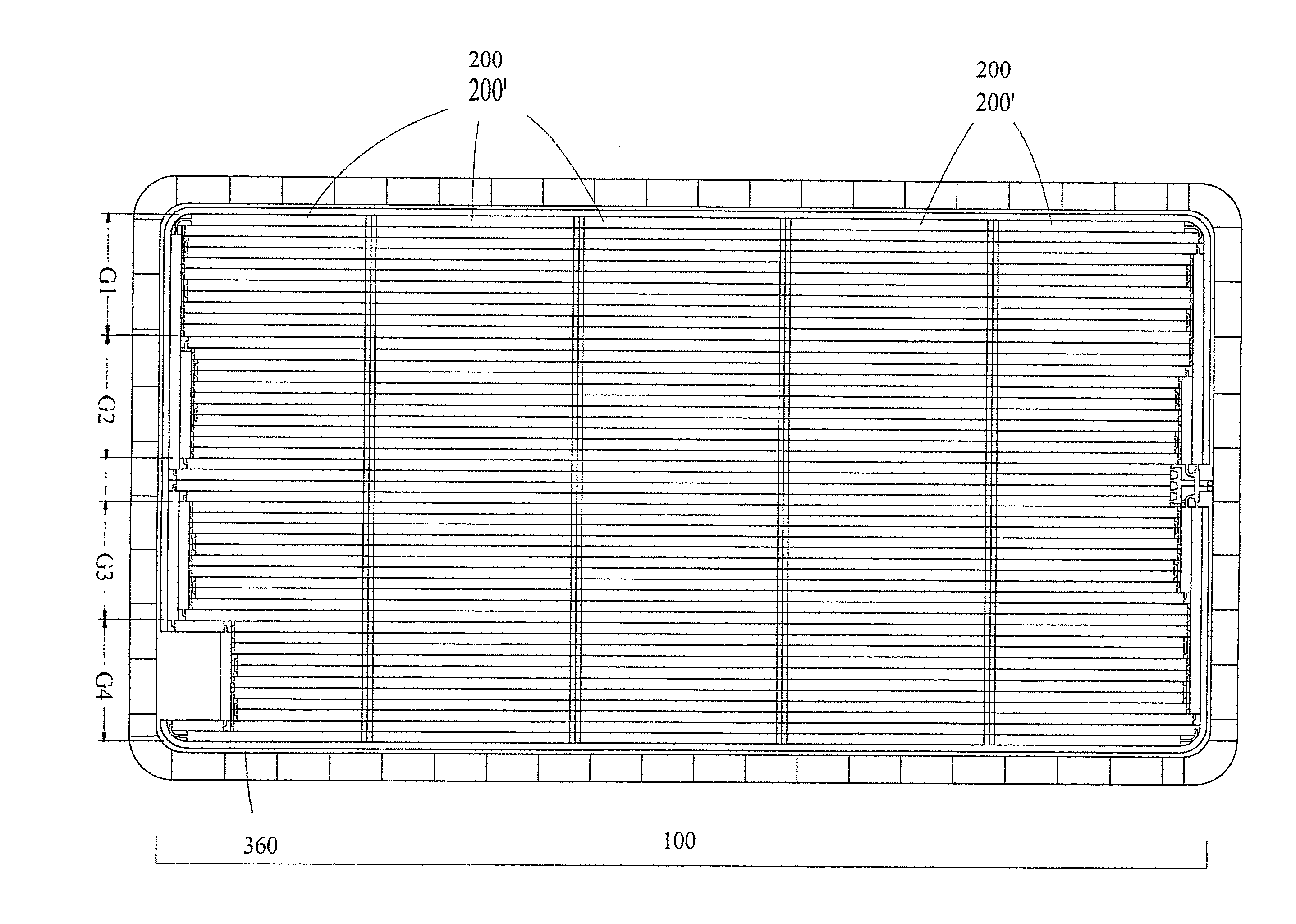
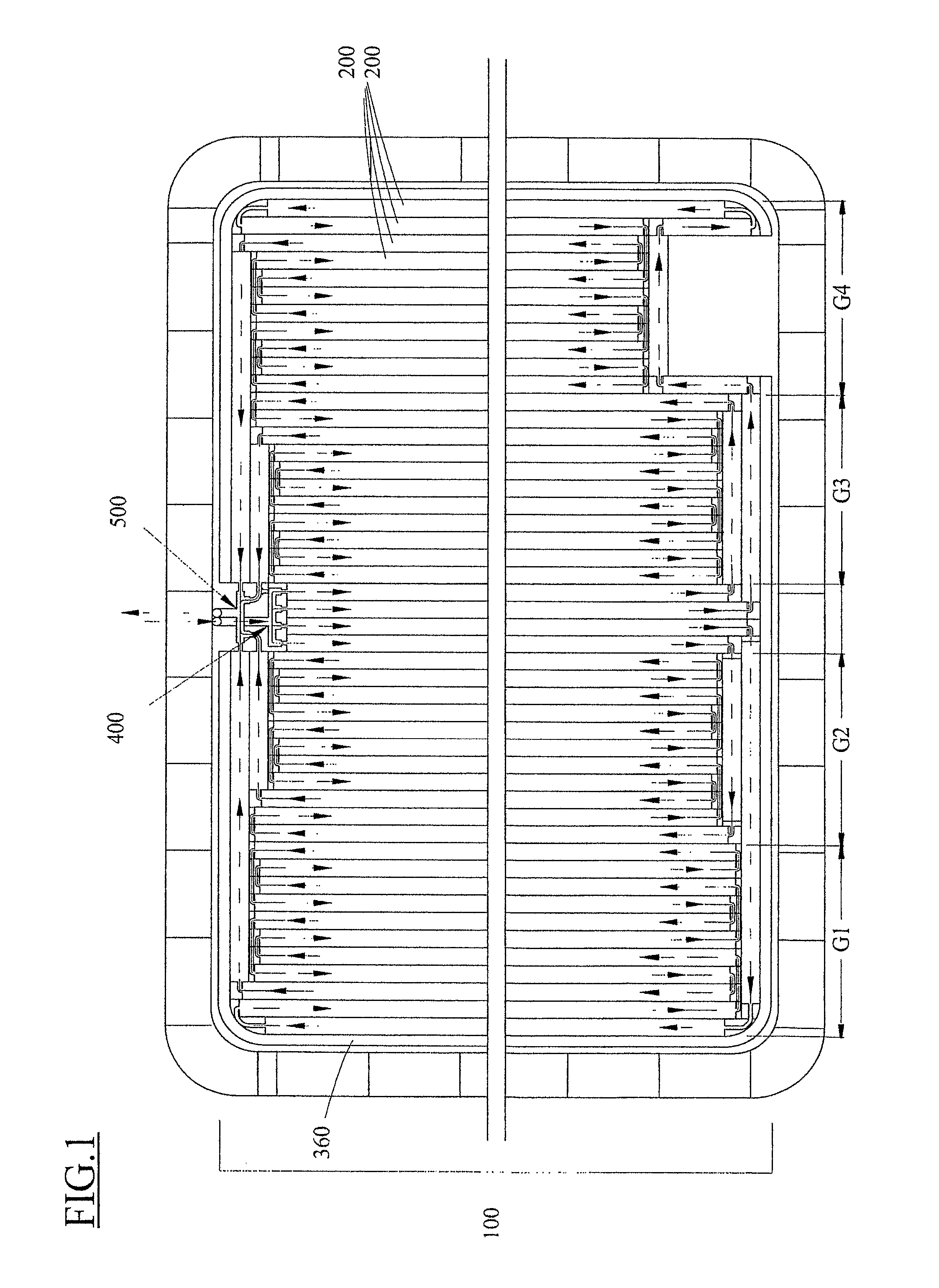
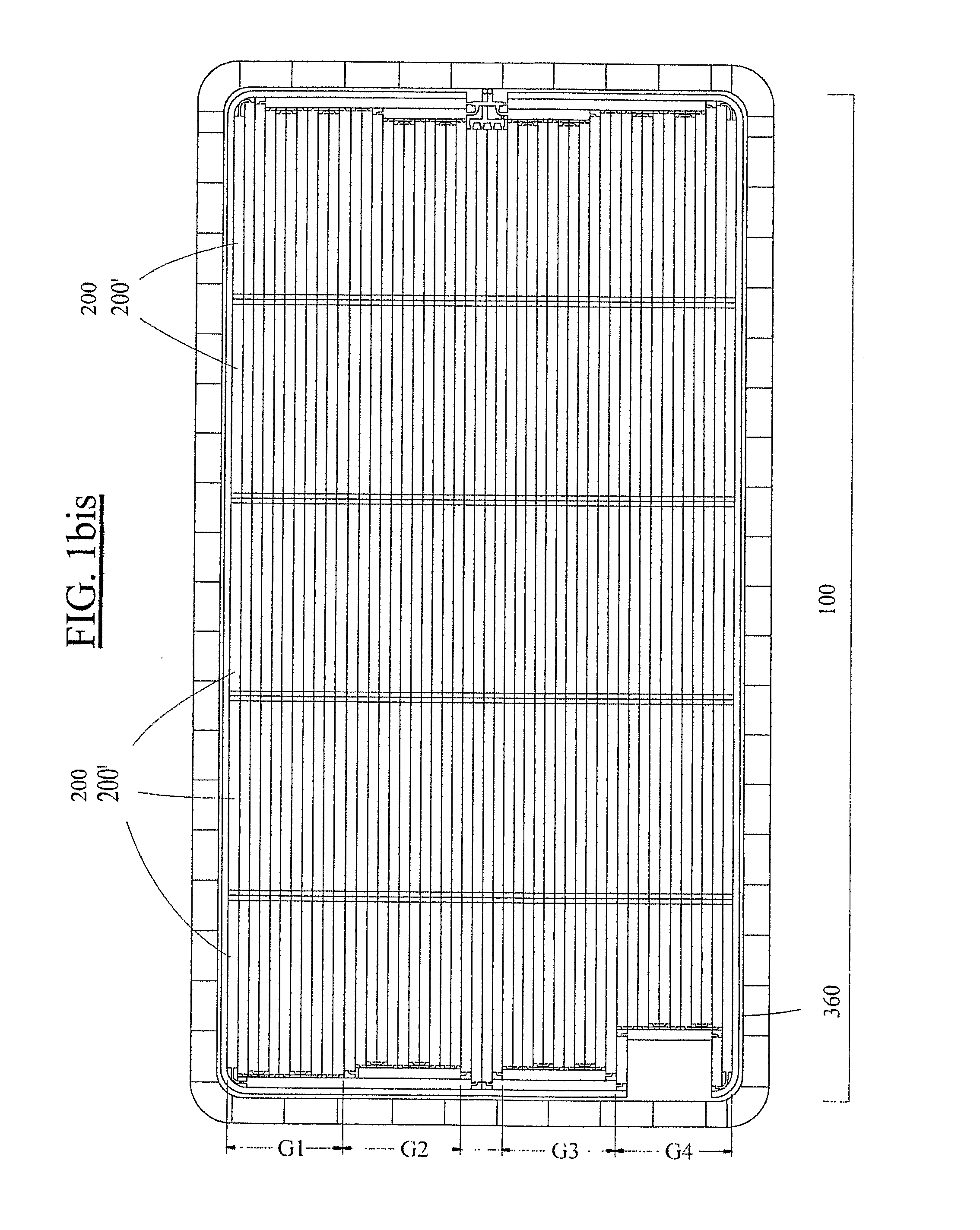
[0087] In FIG. 4c, the profile 200′ shown is a first embodiment variant of the profile 200 described above. The profile 200′ is designed to be used in the structure of the floating floor by being positioned in this floor to rest on a sloping floor of a swimming pool. Indeed, such profiles thus positioned are more complicated to empty, to the extent that when they tilt on contact with the sloping floor during their immersion, they can no longer be emptied completely owing to the fact that the outlet of the channels in the profile is located below the culminating point of the inside volume of the profiles, which has the consequence of imprisoning a volume of air in the upper section of the interior volume of each of these profiles which remain floating or lilt the floating floor.
[0088] This remark is also valid for the profiles that are among the last to be filled that still remain floating whilst the floating floor is resting at the bottom. [0089] On filling, the expulsion point in ...
Example
[0138] In a second embodiment variant of the profile that is shown in FIG. 13, this profile 200″ comprises a plurality of internal cavities 202 arranged side by side.
[0139] A specific multiple type end piece 250′is shown in line with the profile 200″. It is designed to close off each of the extremities of the profile 200″. The end piece 250′is, for this purpose, provided with a plurality of connection means 270 that open out respectively into the internal cavities 202 of the multiple profile 200″.
[0140] The floating floor can be raised more rapidly owing to this construction in which the multiple cavity profile 200″ has a width greater than that of the profiles described above.
[0141] A protective casing realized with a sleeve 310 or a sleeve 320, whose lateral wall is pierced, is mounted on the end piece 250′ closing off the connection end of the profile 200″ to protect it.
Example
[0142] In a third embodiment variant represented in FIG. 14, each profile 200″ is provided with a third conduit 240 arranged between the upper conduit 220 and the upper wall 204. A separating wall 242 separates the upper conduit 220 and the third conduit 240. This conduit is designed to enable the circulation of water under the effect of solar radiation. The profile 200″ must be positioned with its third conduit 240 turned upwards so that the latter can be exposed to the solar radiation. The material constituting the profile 200″′ will be of a dark color and preferably black or dark blue.
[0143] In FIG. 17a, it will be noted that each edge of the separating wall 242 is arranges offset with respect to the end of the profile 200″ according to a distance L3.
[0144] Specific end pieces 250a, 25 Gb shown respectively in FIGS. 15 and 16 are designed to seal one or other of the ends of this profile. Each end piece 250a or 25Gb is provided with a connection means 270 adapted to be connected...
PUM
 Abstract
Description
Claims
Application Information
 - R&D Engineer
- R&D Manager
- IP Professional
- Industry Leading Data Capabilities
- Powerful AI technology
- Patent DNA Extraction
Browse by: Latest US Patents, China's latest patents, Technical Efficacy Thesaurus, Application Domain, Technology Topic, Popular Technical Reports.
© 2024 PatSnap. All rights reserved.Legal|Privacy policy|Modern Slavery Act Transparency Statement|Sitemap|About US| Contact US: help@patsnap.com