Centralized optical-fiber-based wireless picocellular systems and methods

a wireless and picocellular technology, applied in the field of wireless communication systems, can solve the problems of difficult scaling, complicated distribution and use, and relatively complex wireless system/network,

Inactive Publication Date: 2007-12-13
CORNING CABLE SYST LLC
View PDF99 Cites 172 Cited by
  • Summary
  • Abstract
  • Description
  • Claims
  • Application Information

AI Technical Summary

Benefits of technology

This patent describes an optical fiber based network where different services can communicate wirelessly with clients through small cells. There is a main facility called a hub which has equipment to convert between electricity and light. Multiple smaller facilities have these components too. These smaller facilities use optical fibers to connect up to the Hub. Overall this technology allows for efficient and reliable connections across various locations without requiring physical cables.

Problems solved by technology

The technical problem addressed in this patent text relates to improving wireless communication systems by utilizing picocells to provide smaller, more targeted areas of cell coverage without requiring multiple access points to be controlled by one main unit. Current wireless systems require complex wiring between each access point and can struggle to efficiently distribute signals across large regions.

Method used


Image

  • Centralized optical-fiber-based wireless picocellular systems and methods
  • Centralized optical-fiber-based wireless picocellular systems and methods
  • Centralized optical-fiber-based wireless picocellular systems and methods

Examples


Embodiment Construction

[0024]Reference is now made in detail to the present preferred embodiments of the invention, examples of which are illustrated in the accompanying drawings. Whenever possible, the same or analogous reference numbers are used throughout the drawings to refer to the same or like parts.

I. Generalized Optical-Fiber-Based Wireless System

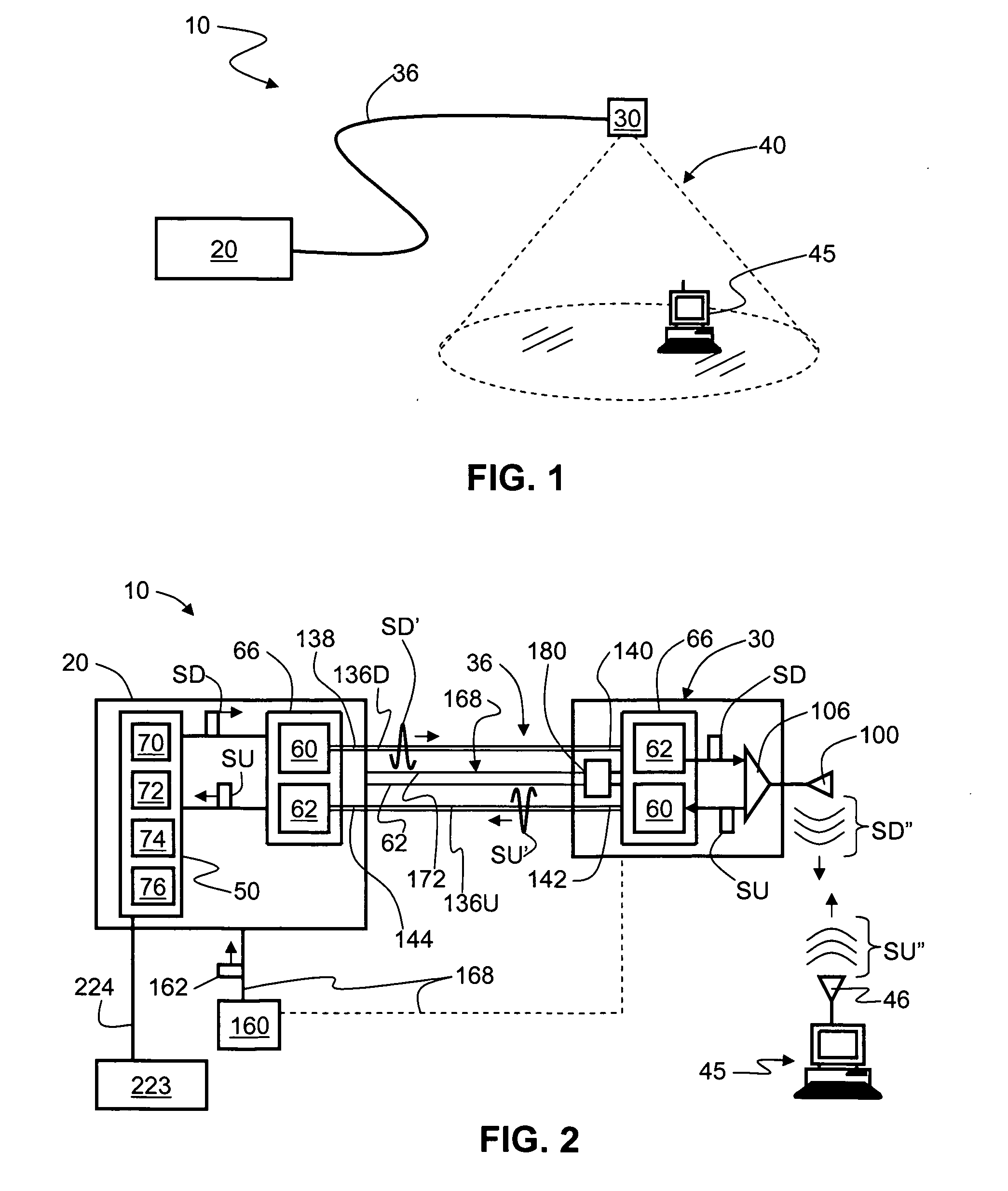
[0025]FIG. 1 is a schematic diagram of a generalized embodiment of an optical-fiber-based wireless picocellular system 10 according to the present invention. System 10 includes a head-end unit 20, a transponder unit (“transponder”) 30 and an optical fiber RF communication link 36 that optically couples the head-end unit to the transponder. As discussed in detail below, system 10 has a picocell 40 substantially centered about transponder 30. Head-end unit 20 is adapted to perform or to facilitate any one of a number of RF-over-fiber applications, such as radio-frequency identification (RFID), wireless local-area network (WLAN) communication, or cellular ph...


PUM


Abstract

The centralized optical-fiber-based wireless picocellular system includes one or more service units at a central head-end station. The one or more service units are optically coupled to one or more transponders via respective one or more optical fiber RF communication links. The transponders are each adapted to provide within the associated picocell electromagnetic RF service signals from different service units, and receive electromagnetic RF service signals from any client device within the picocell. The service signal from the particular client device is sent over the optical fiber RF communication link back to one or more service units. The transponders are arranged along the length of one or more optical fiber cables, which can be distributed throughout a building infrastructure. This creates a picocellular coverage area that provides a number of different wireless services relative to the building infrastructure. The service units can generate the electrical service signals, pass such signals to and from one or more outside networks, and/or coordinate the delivery of the signals between client devices within the picocellular coverage area.

Description


Claims


Application Information

Patent Timeline
Owner CORNING CABLE SYST LLC
Why Eureka
Try Eureka