

Camera and image pick-up device unit used therefor having a sealing structure between a dust-proofing member and an image pick-up device
- Summary
- Abstract
- Description
- Claims
- Application Information
AI Technical Summary
Benefits of technology
Problems solved by technology
Method used
Image

Examples
first embodiment
[0139] First, a description is given of the schematic structure of a camera according to the present invention.
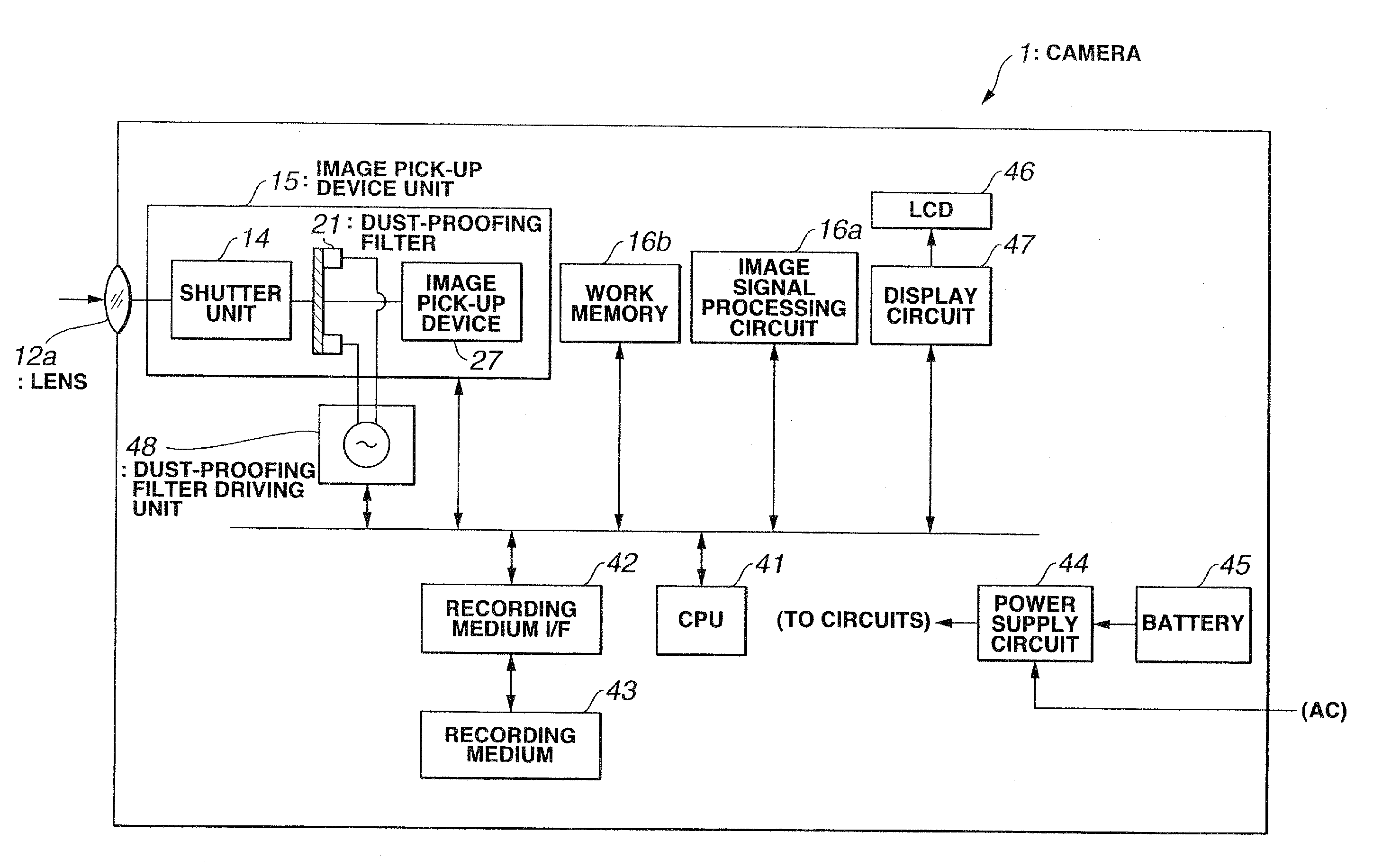
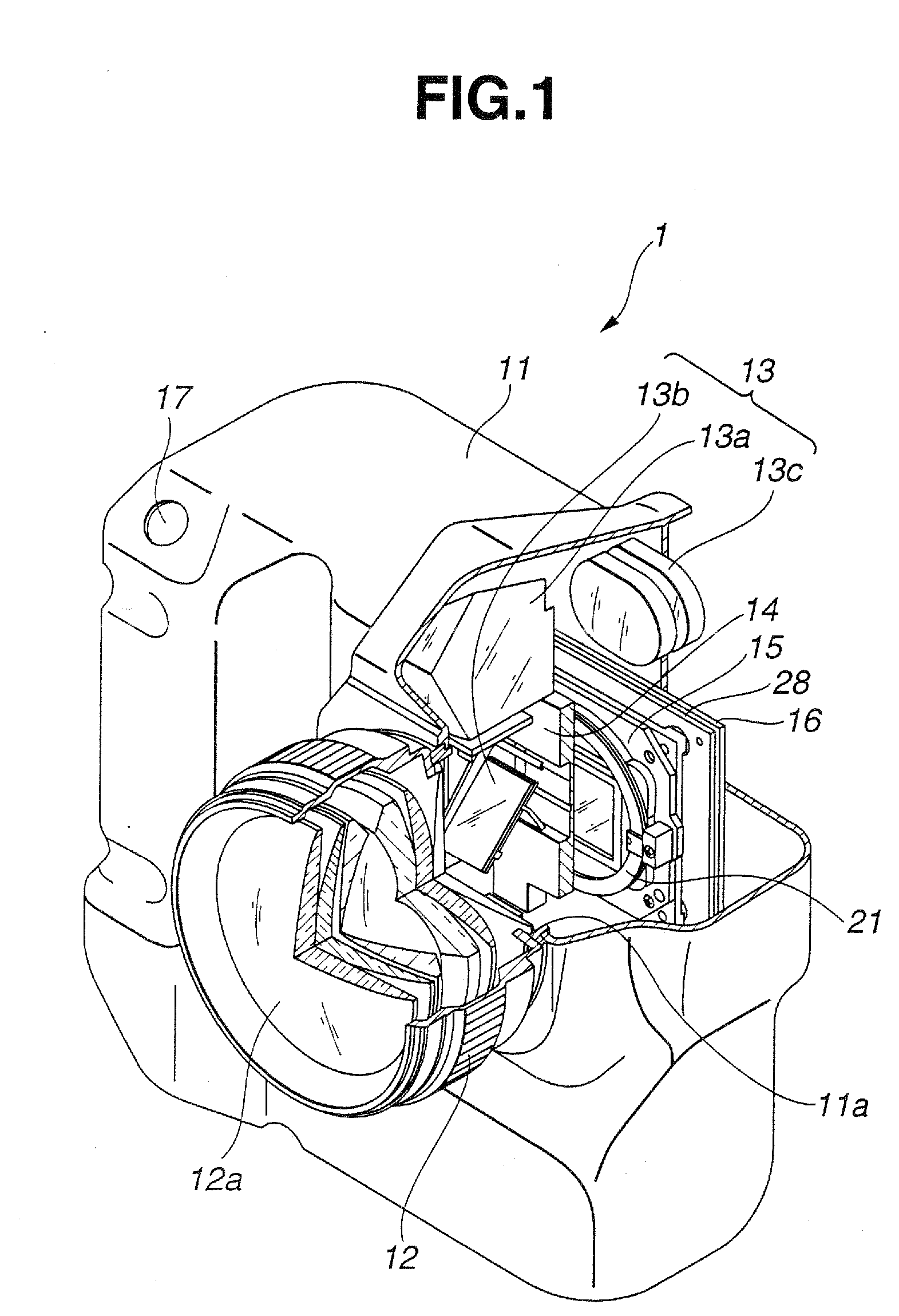
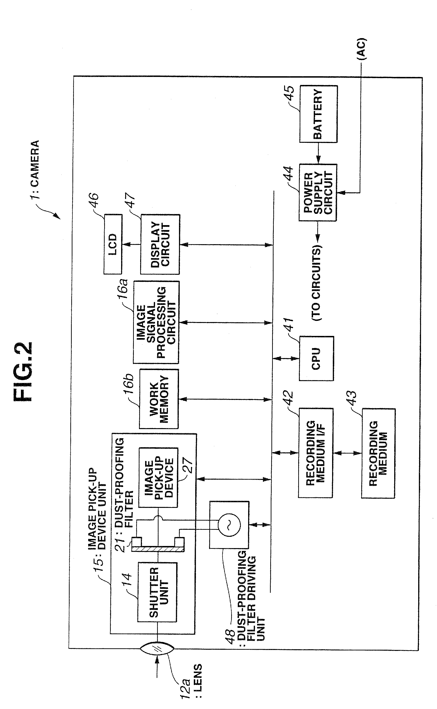
[0140]FIGS. 1 and 2 are diagrams showing the schematic structure of the camera according to the first embodiment of the present invention. FIG. 1 is a perspective view schematically showing the internal structure of a cut-off part of the camera, and FIG. 2 is a block diagram schematically mainly showing the electrical structure of the camera.
[0141] According to the first embodiment, a camera 1 comprises a camera main body unit 11 and a lens barrel 12 which are provided independently. The camera main body unit 11 and the lens barrel 12 are detachable.
[0142] The lens barrel 12 holds a photographing optical system (photographing lenses) 12a comprising a plurality of lenses and a driving mechanism of the lenses. The photographing optical system 12a comprises a plurality of optical lenses through which a subject beams are transmitted so as to form the subject image generated b...
second embodiment
[0208] In the image pick-up device unit 15A of the camera the sealing structure is formed as follows.
[0209] That is, a predetermined void portion 51Aa is formed in a space formed by opposing the optical LPF 25 and the dust-proofing filter 21. On the peripheral side of the optical LPF 25, a space portion 51Ab is formed by the CCD case 33 and the dust-proofing filter 21 to be extended towards the outside of the optical LPF 25. The space portion 51Ab is set to be wider than the void portion 51Aa. A space containing the void portion 51Aa and the space portion 51Ab corresponds to a sealing space 51A which is substantially airtightly sealed by the CCD case 33, the dust-proofing filter 21, and the optical LPF 25.
[0210] As mentioned above, in the image pick-up device unit 15A in the camera according to the second embodiment, the sealing structure includes the sealing space 51A which is formed at the periphery of the optical LPF 25 and the dust-proofing filter 21 and which is substantially...
third embodiment
[0216] In the case of a digital camera using a numerous-pixel type image pick-up device in which the number of valid pixels (the number of pixels used for formation of image data) of the image pick-up device exceeds the resolution of the lens, the image pick-up device unit is formed by excluding the optical LPF in front of the image pick-up device. The present invention can easily be applied in the above-mentioned case. an example will be described hereinbelow.
[0217] In other words, the structure according to the third embodiment is substantially the same as that according to the second embodiment. Unlike the second embodiment, the optical LPF (25) according to the second embodiment is excluded and a CCD case 34 for supporting the dust-proofing filter 21 and for fixing and holding the image pick-up device 27 and the optical LPF (25) is used in place of the CCD case (33) for fixing and holding the image pick-up device 27 and the optical LPF (25). Other structures are the same as tho...
PUM
 Abstract
Description
Claims
Application Information