
Split knife edge seals
a compressor and knife edge technology, applied in the direction of machines/engines, forging/pressing/hammering apparatus, liquid fuel engines, etc., can solve the problems of prone cracking of concentrated stress areas, tensile hoop stress on the outer portion of the disk, and the knife edge seal
- Summary
- Abstract
- Description
- Claims
- Application Information
AI Technical Summary
Benefits of technology
Problems solved by technology
Method used
Image

Examples
Embodiment Construction
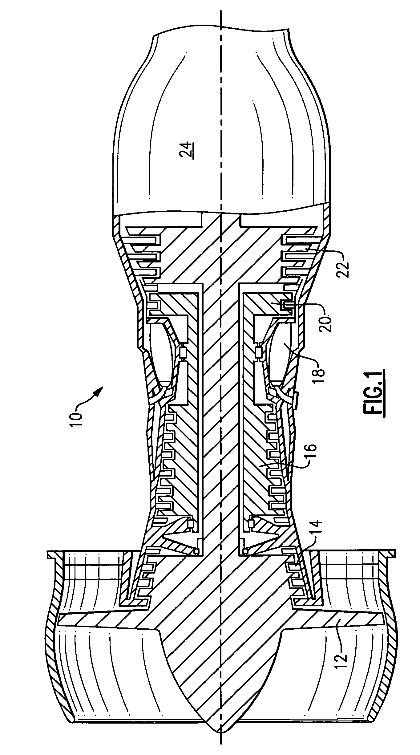
[0021]FIG. 1 is a schematic view of a turbine engine 10. Air is pulled into the turbine engine 10 by a fan 12 and flows through a low pressure compressor 14 and a high pressure compressor 16. Fuel is mixed with the air and combustion occurs within the combustor 18. Exhaust from combustion flows through a high pressure turbine 20 and a low pressure turbine 22 prior to leaving the engine through the exhaust nozzle 24.
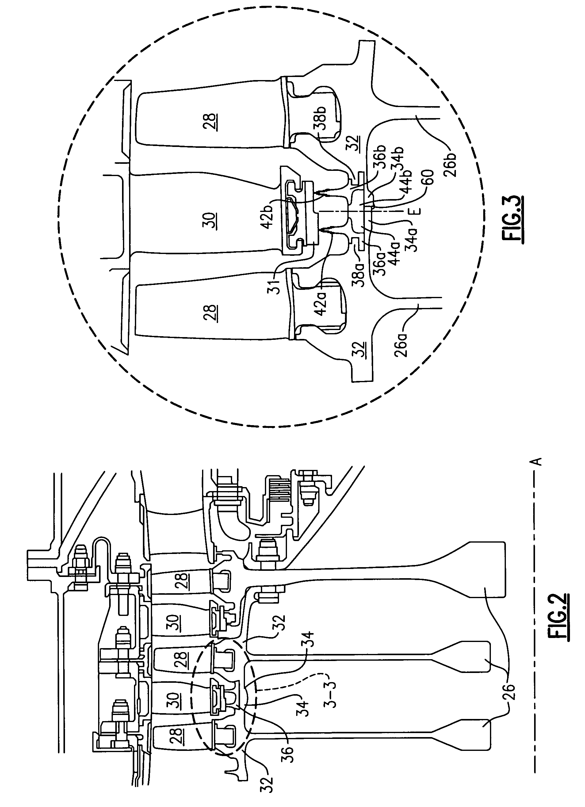
[0022]FIG. 2 illustrates a portion of a cross-section of a typical compressor including multiple disks 26 defining a compressor rotor. Each disk 26 rotates about an axis A located along the centerline of the turbine engine 10. A plurality of rotor blades 28 are mounted about the circumference of each of the disks 26. A plurality of stator vanes 30 extend between the rotor blades 28 of axially adjacent disks 26, as shown.
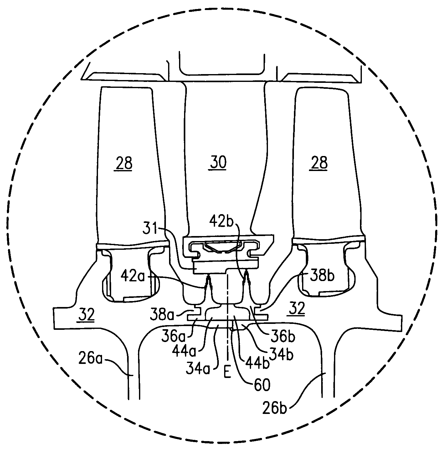
[0023]Each disk 26 includes a disk rim 32. The disk rim 32 supports the rotor blades 28. A backbone 34 extends from each disk rim 32. A plurality of knife...
PUM
| Property | Measurement | Unit |
|---|---|---|
| circumference | aaaaa | aaaaa |
| pressure | aaaaa | aaaaa |
| compressive | aaaaa | aaaaa |
Abstract
Description
Claims
Application Information