
System for supplying a turbine engine with fluid having a low pressure pumping assembly comprising two pumps in parallel

a technology of low pressure pumping and turbine engine, which is applied in the direction of engine components, machine/engine, feed system, etc., can solve the problems of reducing the overall performance of the turbomachine comprising the supply system, generating significant heat energy dissipation of excess fuel flowing in the fluid recirculation loop, etc., to reduce handling and manufacturing costs, simplify the integration of low pressure pumps, and reduce energy withdrawal

Active Publication Date: 2020-01-07
SN DETUDE & DE CONSTR DE MOTEURS DAVIATION S N E C M A
View PDF17 Cites 1 Cited by
  • Summary
  • Abstract
  • Description
  • Claims
  • Application Information

AI Technical Summary

Benefits of technology

The invention is a low pressure assembly for a turbomachine that improves energy efficiency during different phases of flight. It achieves this by using two centrifugal pumps, located head to foot, that work together to balance axial strains and reduce energy withdrawal. This design also reduces manufacturing and handling costs and limits recirculation events between the primary and secondary loops. Overall, the invention achieves a better compromise between energy efficiency and performance.

Problems solved by technology

However, this excess fuel flowing in the fluid recirculation loop generates a significant heat energy dissipation.
As a result, there is a decrease in the overall performances of a turbomachine comprising the supply system.

Method used


Image

  • System for supplying a turbine engine with fluid having a low pressure pumping assembly comprising two pumps in parallel
  • System for supplying a turbine engine with fluid having a low pressure pumping assembly comprising two pumps in parallel
  • System for supplying a turbine engine with fluid having a low pressure pumping assembly comprising two pumps in parallel

Examples


Embodiment Construction

[0033]Identical, similar or equivalent parts of the different figures bear the same reference numerals so as to facilitate switching from one figure to the other.

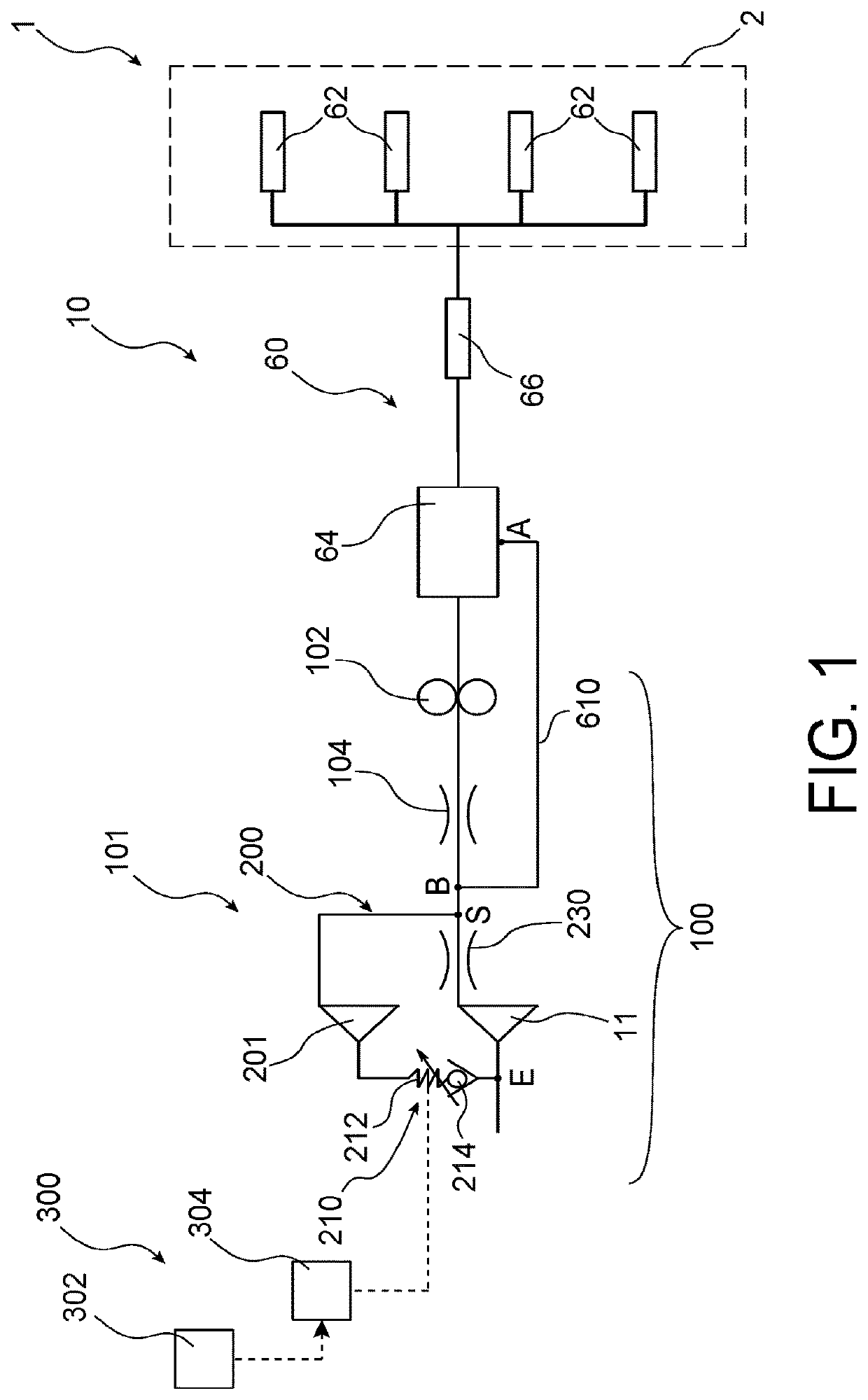
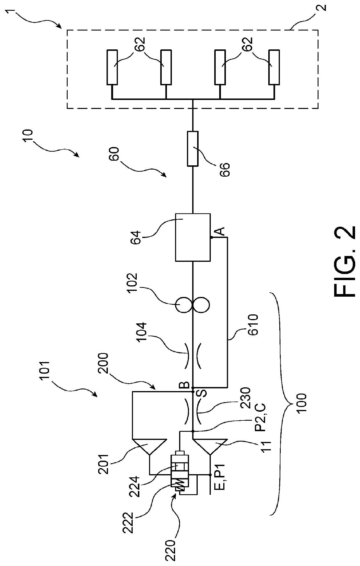
[0034]FIG. 1 represents a system 10 for supplying an aircraft turbomachine 1 with fluid. In the described embodiment, the fluid is fuel. However, when the turbomachine 1 comprises a differential reducer (not represented) configured to rotatably drive at least one propeller, the fluid can also be a lubricant, typically oil.

[0035]The turbomachine 1 comprises a combustion chamber 2 and the fuel supply system 10 of the combustion chamber 2. The combustion chamber 2 comprises a plurality of fuel injectors and fuel injecting systems 62. The injection systems 62 cooperate with the injectors to supply the combustion chamber 2 with the fuel passing through the supply system 10.

[0036]The supply system 10 comprises an upstream circuit 100 and a downstream circuit 60 connected to the upstream circuit 100. The upstream circuit 100 is fo...


PUM


Abstract

A system for supplying a turbine engine with fluid includes a first low-pressure pump, a downstream hydraulic resistance and a high-pressure volumetric pump located between the first low-pressure pump and the downstream hydraulic resistance. The downstream hydraulic resistance includes at least one element selected among a fluid proportioning unit, a filter, a flow meter, an exchanger, a cut-off valve and an injection system. The supply system includes a second low-pressure pump and a supply variator configured such as to vary the flow of fluid supplied to the second low-pressure pump, the second low-pressure pump and the supply variator being located parallel to the first low-pressure pump.

Description

TECHNICAL FIELD[0001]The invention relates to the general technical field of aircraft turbomachines such as turbojet engines and turboprop engines. More precisely, the invention belongs to the technical field of systems for supplying fluid, in particular lubricant or fuel, for a turbomachine.BACKGROUND OF THE INVENTION[0002]A turbomachine fuel supply system, according to a known design of the state of the art, comprises a low pressure pump configured to increase the pressure of the fuel which flows to a high pressure volumetric pump after passing through a hydraulic resistance. The low pressure pump is in particular a centrifugal pump.[0003]The high pressure volumetric pump is for supplying fluid at a constant flow rate both to a supply circuit having variable geometries and a fuel supply circuit of a combustion chamber. The fuel supply circuit of the combustion chamber comprises a fuel metering system configured to control the fuel flow rate towards the injection systems of the com...

Claims


Application Information

Patent Timeline
Patent Type & Authority Patents(United States)
IPC IPC(8): F02C7/236
CPCF02C7/236F05D2240/40F05D2260/98
Inventor WAISSI, BELLALVERTENOEUIL, PHILIPPE
Owner SN DETUDE & DE CONSTR DE MOTEURS DAVIATION S N E C M A
Learn More