

Golf club
- Summary
- Abstract
- Description
- Claims
- Application Information
AI Technical Summary
Benefits of technology
Problems solved by technology
Method used
Image

Examples
first embodiment
[0054] Hereinafter, an embodiment of a golf club according to the invention is described.
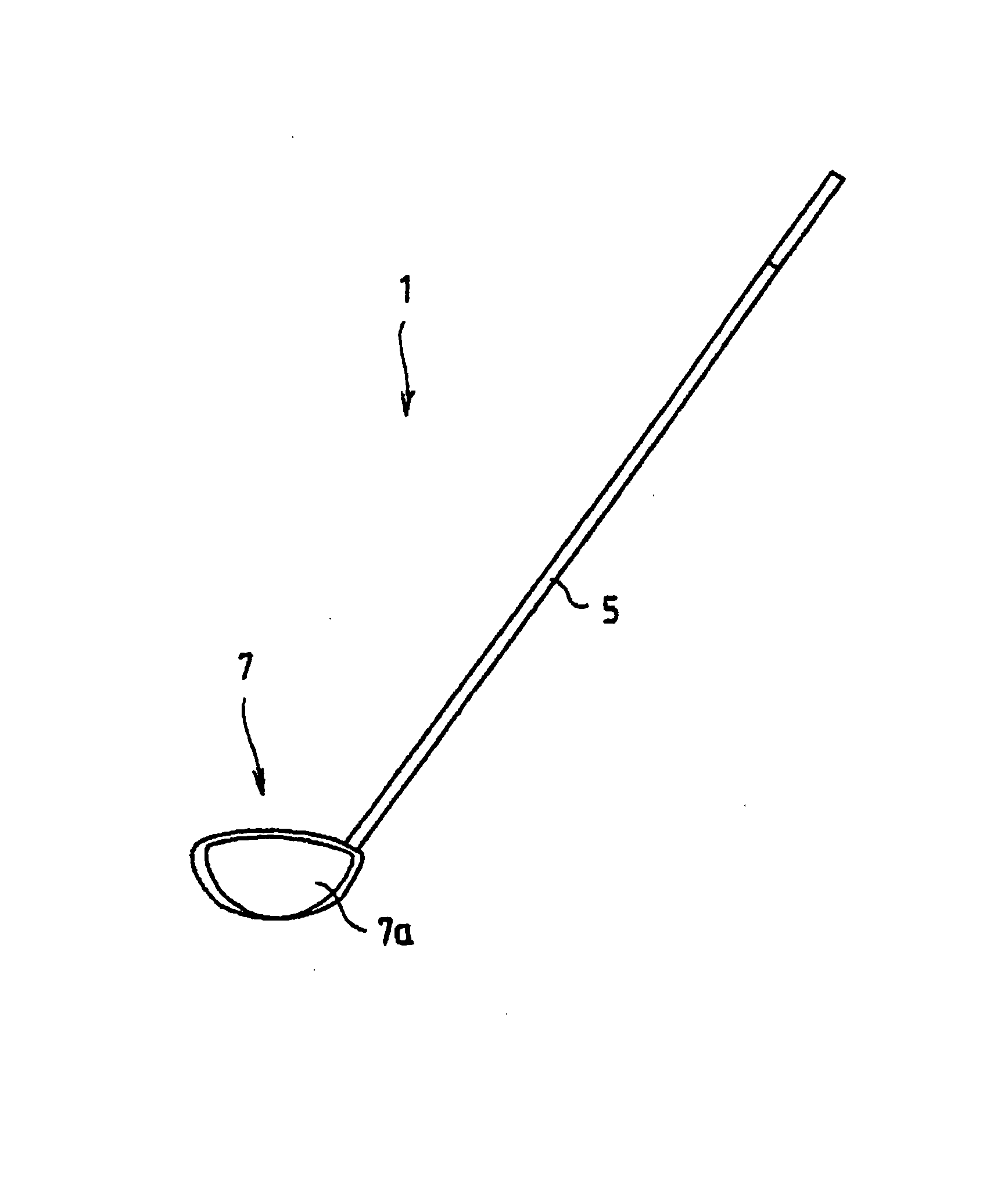
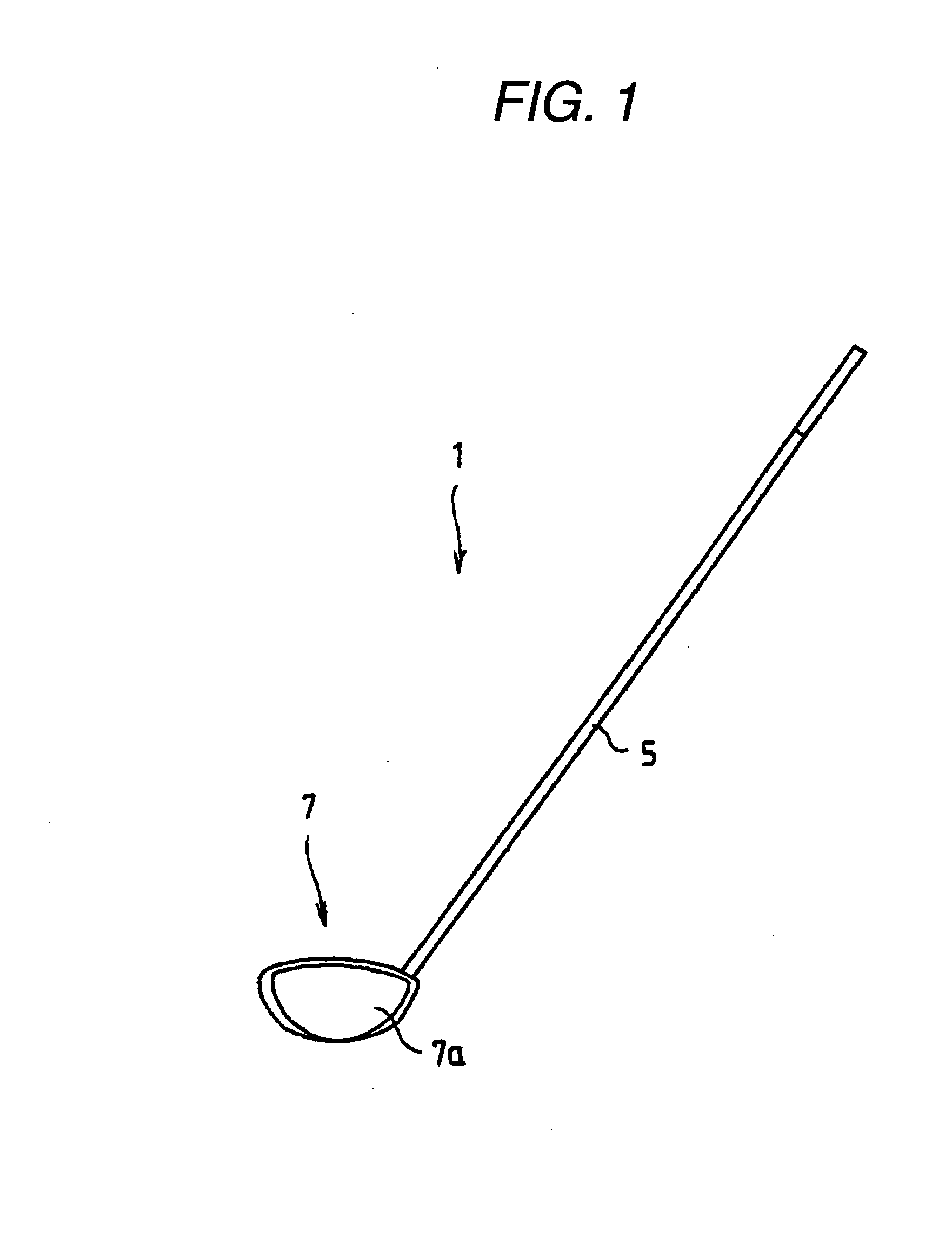
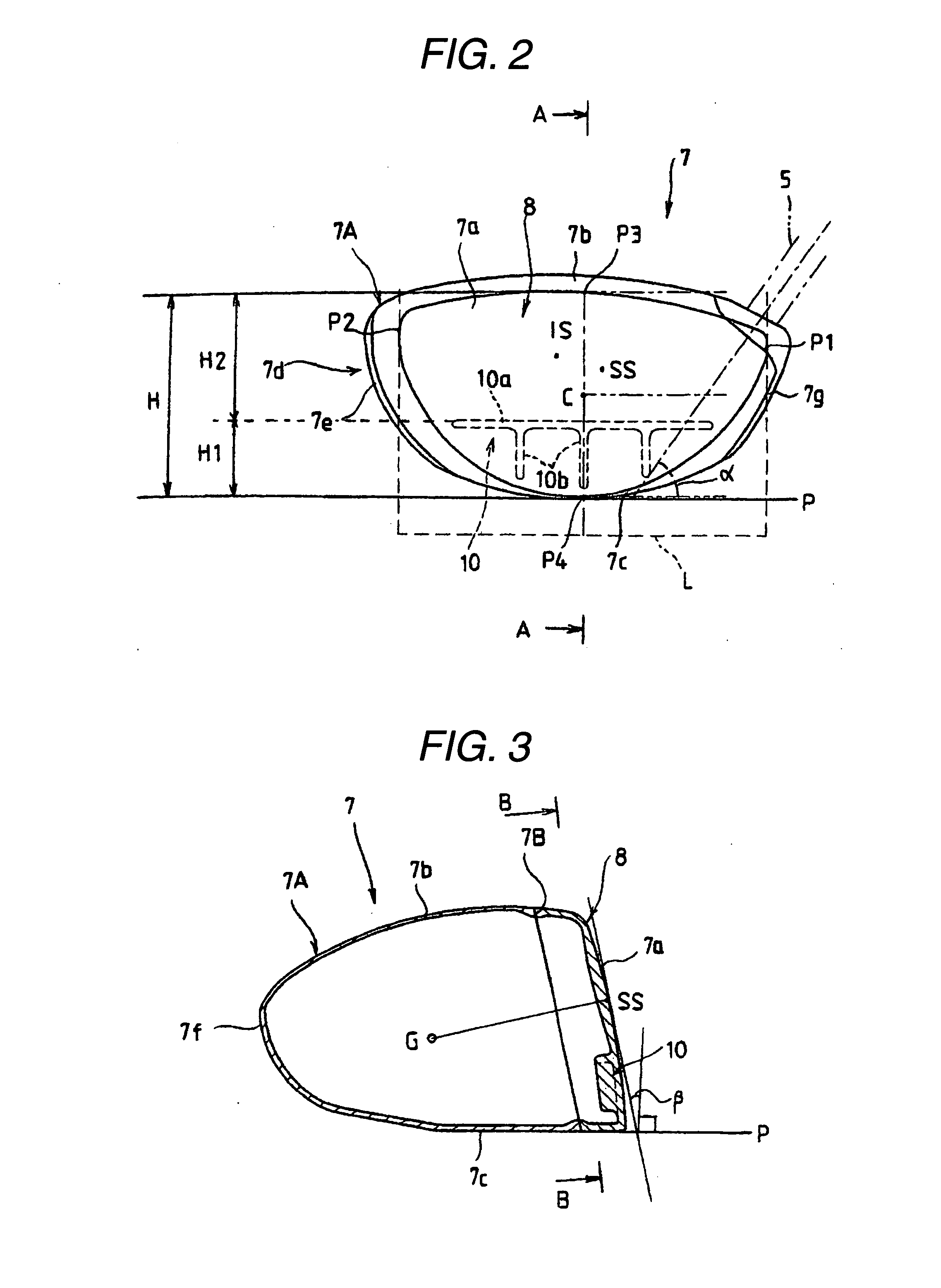
[0055] FIGS. 1 to 5B are views illustrating a first embodiment of the golf club according to the invention. FIG. 1 is a front view illustrating the golf club. FIG. 2 is a front view of a head. FIG. 3 is a cross-sectional view taken along line A-A shown in FIG. 2. FIG. 4 is a cross-sectional view taken along line B-B shown in FIG. 3. FIGS. 5A and 5B are cross-sectional views illustrating modified states of a face portion at hitting of a ball.
[0056] A golf club 1 according to the present embodiment is constituted by fixedly attaching a head 7, which is set to have a predetermined lie angle α and a predetermined loft angle β with respect to a reference horizontal plane P, to an end of a shaft 5 made of metal or FRP (Fiber-Reinforced Plastics). In this case, a head body 7A constituting the head 7 is formed into a hollow structure that has a face portion 7a including a ball hitting surface, and tha...
second embodiment
[0072]FIGS. 6 and 7 are views illustrating a second embodiment of the invention. FIG. 6 is a central cross-sectional view of a head. FIG. 7 is a cross-sectional view taken along line C-C shown in FIG. 6.
[0073] Similarly to the first embodiment, the second embodiment is configured so that when a face member 8 is formed into a predetermined cup-like shape, an end portion of the rib 10 to be formed integrally with the side portion and the sole portion is formed to reach the side portion (a toe part and / or a heel part in the case of the transverse rib 10a) and the sole portion (in the case of the longitudinal rib 10b). The rib 10 is formed integrally with the side portion and the sole portion.
[0074] With such a configuration, the specific rigidity and the specific strength of the lower-side part of the face portion 7a are further increased. When a ball is hit, the entire face portion becomes more difficult to bend. Thus, the loss of energy can effectively be suppressed. In a case wher...
third embodiment
[0076]FIGS. 8 and 9 are views illustrating a third embodiment of the invention. FIG. 8 is a central cross-sectional view of a head. FIG. 9 is a cross-sectional view taken along line D-D shown in FIG. 8.
[0077] According to the present embodiment, a lower-side part (i.e., a rib formation region) of a face portion 7a is formed integrally with a head body 7A. Also, a transverse rib 10a and a longitudinal rib 10b are formed integrally with each other. Similarly to the aforementioned first and second embodiments, a face member 8A is formed by being backwardly bent so as to constitute a part of a crown portion, a toe portion and a heel portion. However, a sole-side edge part of the face member 8A is connected and fixed to a step-like portion 10c formed at the front end side of the transverse rib 10a, without being bent-formed. That is, the transverse rib 10a is placed at a connection portion serving as a lower edge of the face member 8A. Consequently, the strength of the connection portio...
PUM
 Abstract
Description
Claims
Application Information