System for Routing Electronic Mails

a technology of electronic mail and call routing, which is applied in the field of intelligent call routing systems, can solve the problems of a call center system, a very limited number of call routing, and a switch, although increasingly computerized, that cannot be operated,

US20080046531A1Inactive Publication Date: 2008-02-21SHTIVELMAN YURI +10
15 Cites 25 Cited by

Patent Information

Authority / Receiving Office
US · United States
Patent Type
Applications(United States)
Current Assignee / Owner
Publication Date
2008-02-21
Estimated Expiration
Not applicable · inactive patent

Smart Images

  • Figure 1
    Figure 1
  • Figure 2
    Figure 2
  • Figure 3
    Figure 3
Patent Text Reader

Abstract

A computerized telephony call center for serving a customer base has a central switch connected to a plurality of telephones at operator workstations and adapted to route calls to individual ones of the telephones, and also connected to a public switched telephone network, and a first processor connected to the central switch by a high-speed data link and to the telephone network by a digital network connection. The first processor is adapted to monitor transactional activity of the central switch, to process the activity information according to selected routines in the processor, and to communicate processed information to a second processor over the digital network connection. The digital network connection may be a TCP\IP connection. In a preferred embodiment the first processor is connected by a local area network (LAN) to network interfaces including a video display unit (VDU) and input apparatus proximate individual ones of the plurality of telephones connected to the central switch. In some embodiments the LAN is also connected to a data server running an instance of a database. In other embodiments the call center, and other similar call centers are all part of a call routing system wherein calls are routed from Service Control Points to call centers over telephone lines, and data is routed to the call centers over a separate digital network connection between processors coupled to the Service Control Points and to the call center central switches. In various embodiments aspects of the invention apply to Internet protocol network telephony (IPNT) calls as well as to conventional telephony calls.
Need to check novelty before this filing date? Find Prior Art

Description

CROSS-REFERENCE TO RELATED DOCUMENTS

[0001] The present patent application is a Continuation application of copending patent application Ser. No. 08 / 948,530, filed Oct. 9, 1997, which is a divisional application of Ser. No. 08 / 928,410, filed Sep. 12, 1997 (now U.S. Pat. No. 6,064,667), which is a CIP of Ser. No. 08 / 866,357 filed on Feb. 10, 1997, which is a CIP of application Ser. No. 08 / 802,660. The present application is also a Continuation of applications having the Ser. No. 09 / 096,729 filed Jun. 11, 1998, Ser. No. 09 / 574,315 filed May 19, 2000, Ser. No. 09 / 592,182 filed Jun. 12, 2000, Ser. No. 09 / 659,933 filed Sep. 12, 2000, and Ser. No. 09 / 561,139 filed Apr. 28, 2000. The prior applications are all incorporated herein in their entirety by reference.FIELD OF THE INVENTION

[0002] The present invention is in the area of telephone call processing and switching, and pertains more particularly to intelligent call-routing systems. BACKGROUND OF THE INVENTION

[0003] Telephone call proc...

Examples

Embodiment Construction

General Description

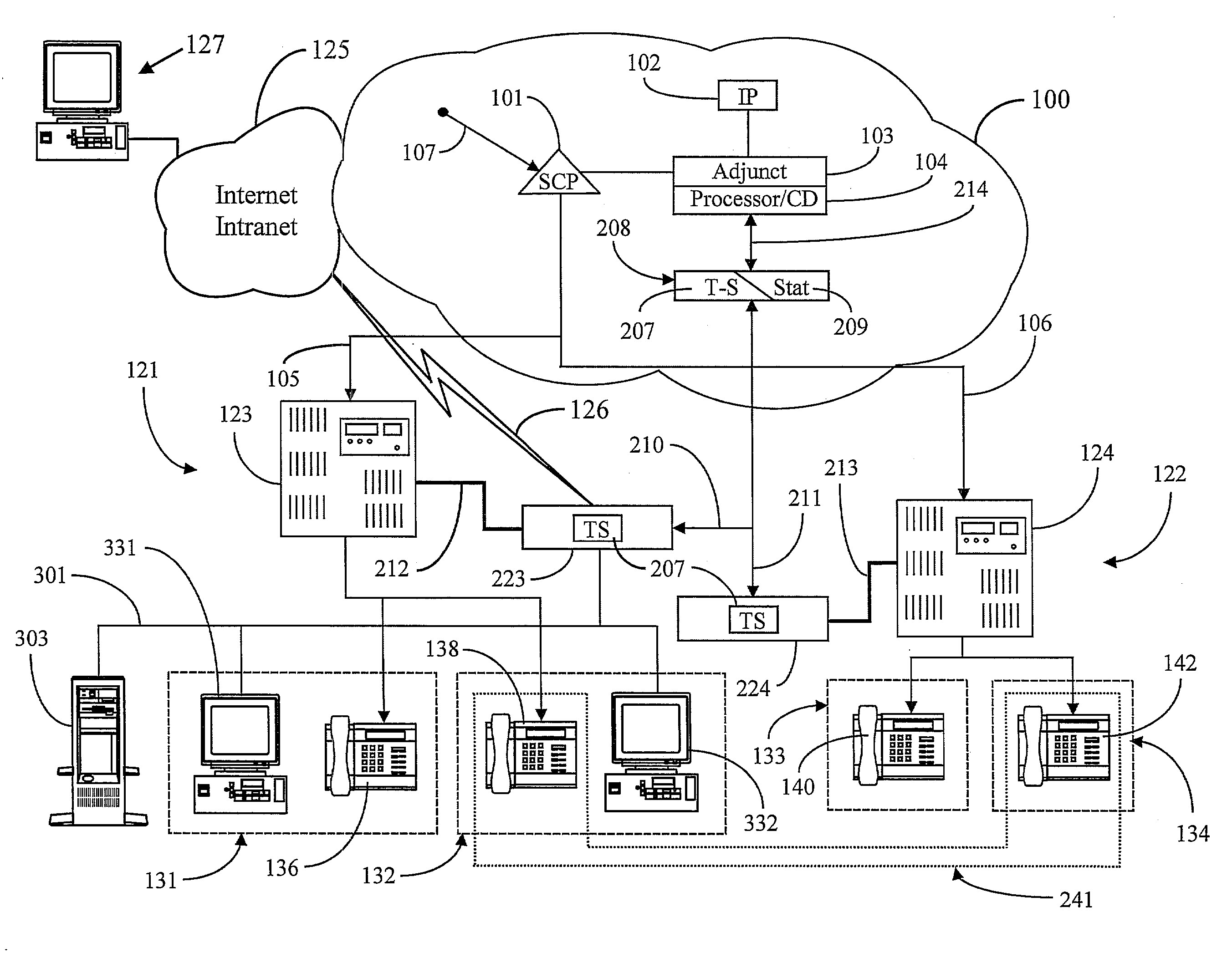
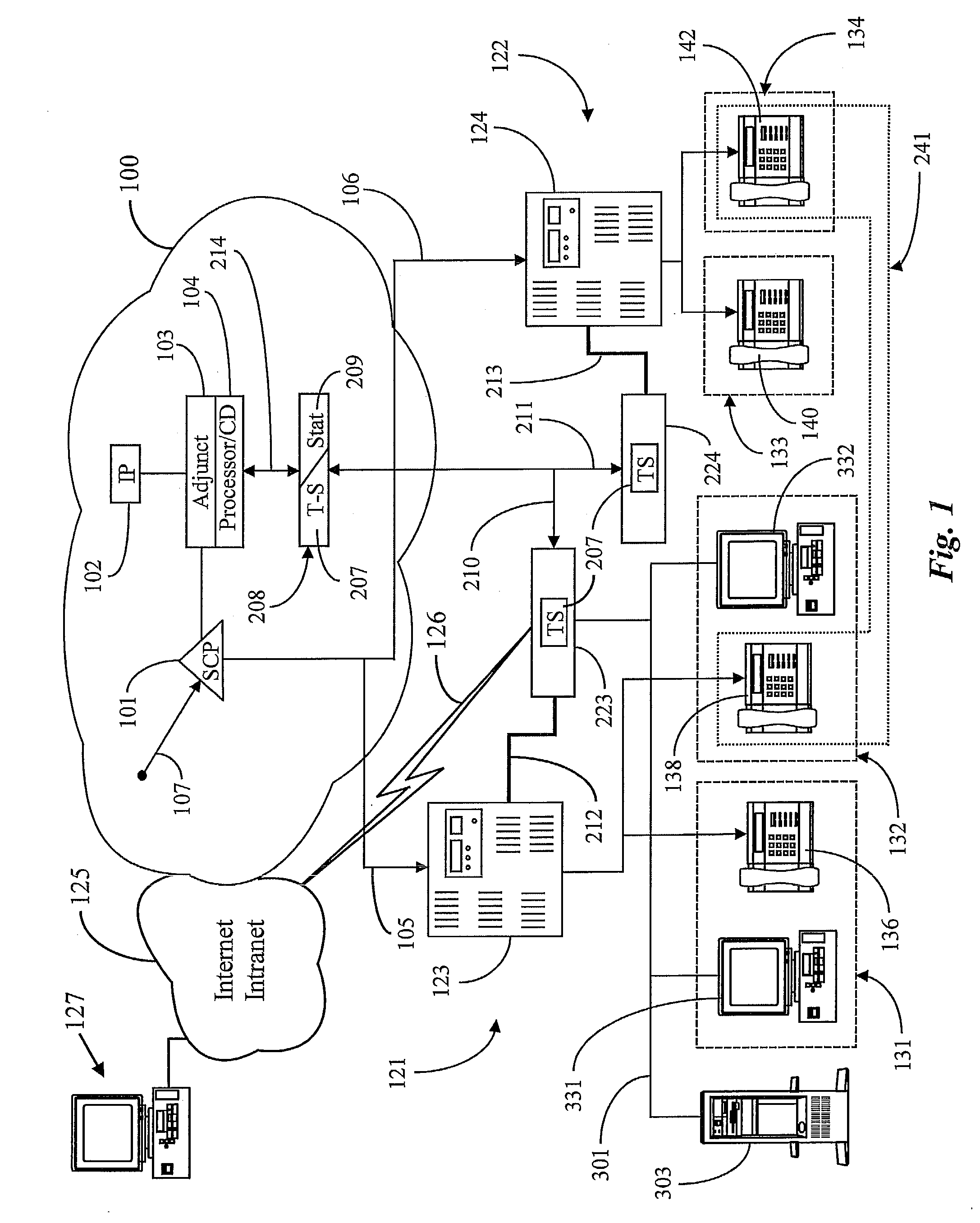
[0043]FIG. 1 is a system diagram of a call-routing system according to a preferred embodiment of the present invention, comprising two call centers 121 and 122. In this embodiment there may be many more than the two call centers shown, but two is considered by the inventors to be sufficient to illustrate embodiments of the invention. Each of call centers 121 and 122 includes a telephony switch (switch 123 for center 121 and switch 124 for center 122) providing routing to individual agent stations.

[0044] Call centers 121 and 122 in FIG. 1 are CTI-enhanced by virtue of a processor connected by a high-speed data link to the associated call center switch. At call center 121, processor 223 is connected by link 212 to switch 123, and at call center 122, processor 224 is connected to switch 124 by link 213. Each processor 223 and 224 includes an instance of a CTI application 207 known to the inventors as T-Server (T-S) 207. Further, each processor 223 and 224 at each ...