Piezoelectric power supply

a power supply and piezoelectric technology, applied in piezoelectric/electrostrictive/magnetostrictive devices, piezoelectric/electrostriction/magnetostriction machines, electrical equipment, etc., can solve the problems of increasing the burden on manufacturers and consumers, reducing the cost and production process, and improving product competitiveness.

Inactive Publication Date: 2008-02-28
ZIPPY TECH
View PDF8 Cites 7 Cited by
  • Summary
  • Abstract
  • Description
  • Claims
  • Application Information

AI Technical Summary

Benefits of technology

[0006]Therefore the primary object of the present invention is to provide a piezoelectric power supply that has a high voltage output unit to supply power required by a high voltage load such as a gas discharge lamp through a first piezoelectric plate and a low voltage output unit to supply power required by peripheral devices such as speakers, small lamps, ear sets, USB connection ports and the like through a second piezoelectric plate. Thereby cost and production process can be reduced, and more LCD features can be provided to improve product competitiveness.

Problems solved by technology

All the aforesaid approaches result in a higher cost and a longer production process.
They create a greater burden to manufacturers and consumers.

Method used


Image

  • Piezoelectric power supply
  • Piezoelectric power supply
  • Piezoelectric power supply

Examples


Embodiment Construction

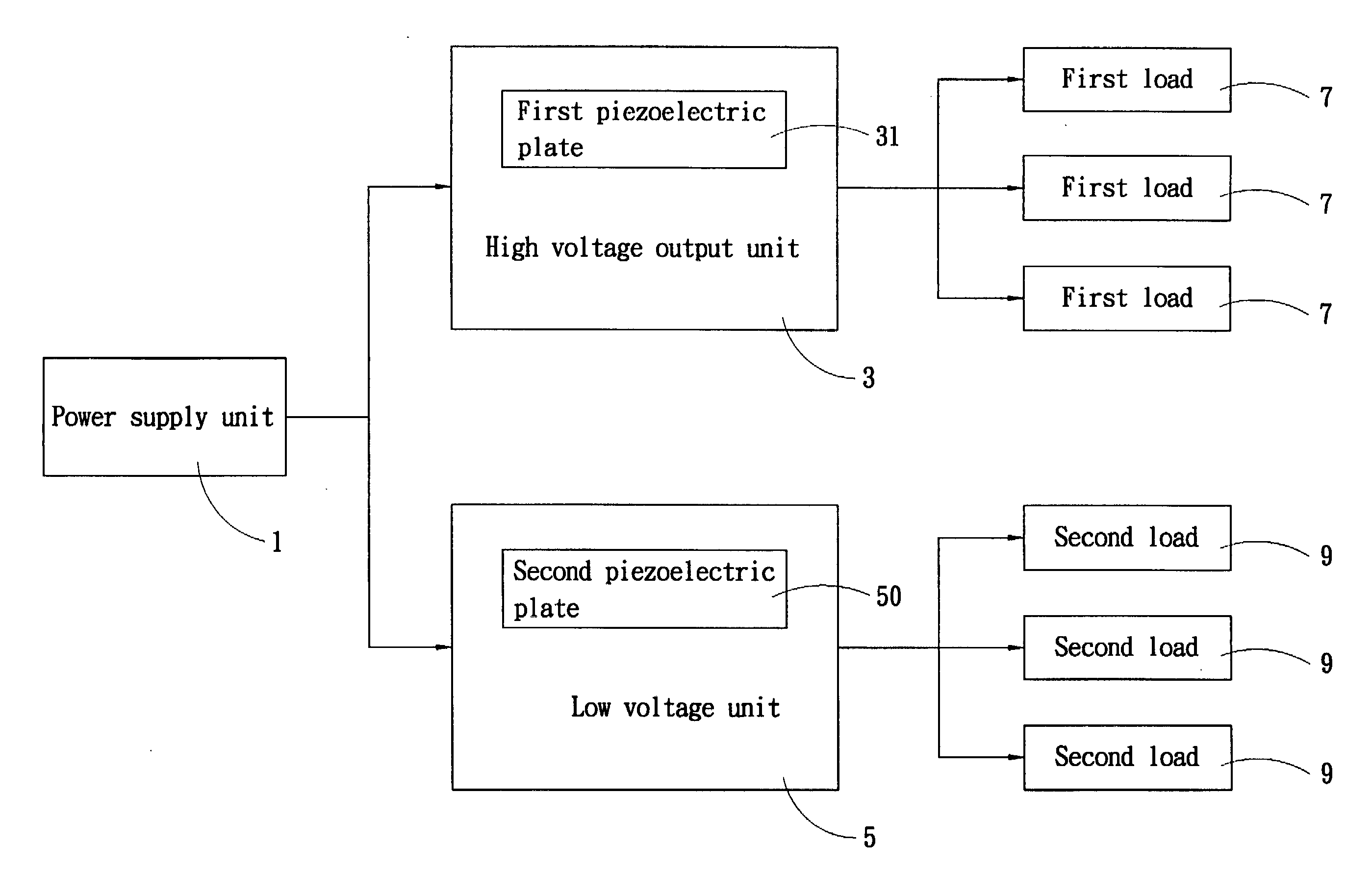
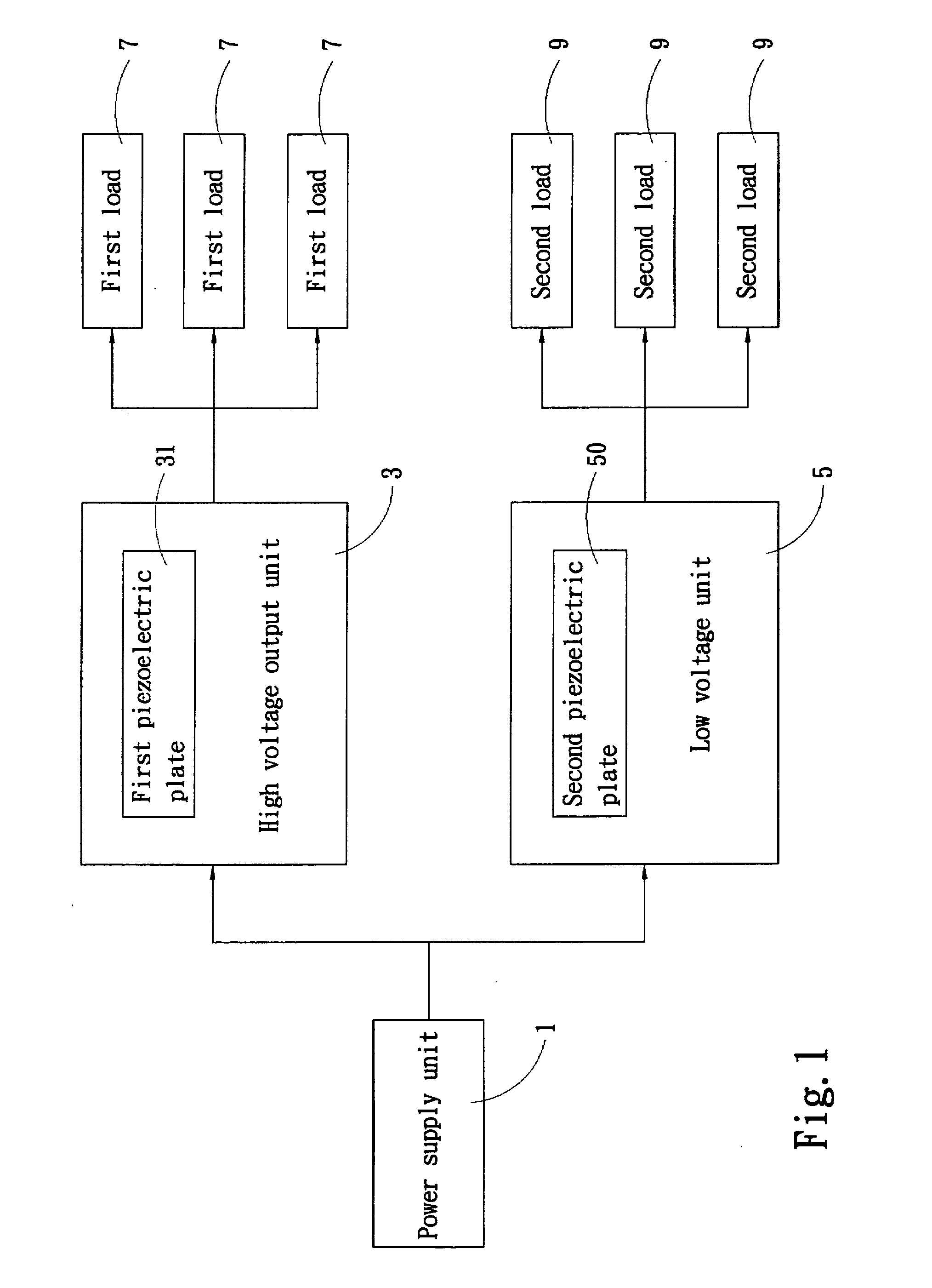
[0012]Please refer to FIG. 1 for an architecture block diagram of a first embodiment of the invention. The piezoelectric power supply of the invention aims to provide a low voltage power and a high voltage power. It includes a power supply unit 1 to receive city AC power and transform to DC intermediate voltage power to be output, a high voltage output unit 3 which has a first piezoelectric plate 31 to transform the power output from the power supply unit 1 to AC high voltage power to output and supply at least one first load 7, and a low voltage output unit 5 which has a second piezoelectric plate 50 to transform the power output from the power supply unit 1 to AC low voltage power to output and supply at least one second load 9. The first piezoelectric plate 31 and the second piezoelectric plate 50 may be laminated piezoelectric plates or a single piezoelectric plate.

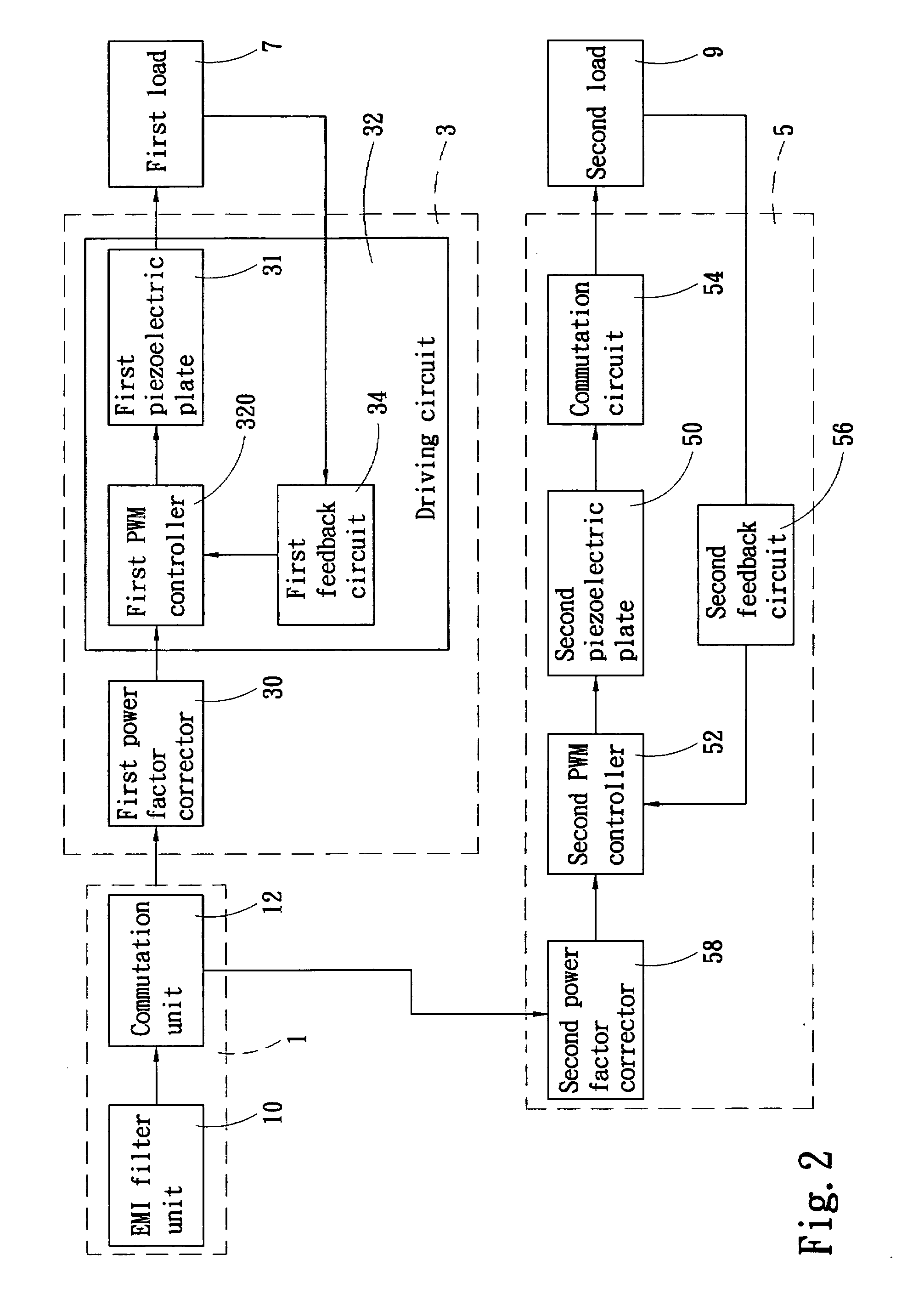
[0013]Refer to FIG. 2 for another architecture block diagram of the first embodiment of the invention. The power su...


PUM


Abstract

A piezoelectric power supply includes a power supply unit to provide DC intermediate voltage power output to drive a high voltage output unit of a first load through a first piezoelectric plate and a low voltage output unit of a second load through a second piezoelectric plate. Thereby the power supply can provide a low voltage secondary power output to reduce cost and improve power output flexibility and efficiency. It can be used on display devices such as gas discharge lamps, and also provide additional low voltage secondary power for peripheral devices such as speakers, lamps, ear sets, USB connection ports and the like.

Description

FIELD OF THE INVENTION[0001]The present invention relates to a power supply and particularly to a piezoelectric power supply.BACKGROUND OF THE INVENTION[0002]In recent years LCD technology has been well developed, the cost of LCD drops significantly. As a result, it gradually replaces the traditional CRT in the home appliances. The competition in the market place is fierce. To provide distinguished product features is a high priority R & D issue in the LCD market. For instance, R.O.C. patent publication No. 200534569 discloses two types of driving circuits. The first type of driving circuit provides an AC signal from a power source to a power supply, then the power supply transforms voltage to output an electric signal to an inverter to boost the voltage and output a high voltage electric signal. The present power supply to process the AC signal output from the power source includes an electromagnetic interference (EMI) filter unit, a commutation unit, a power factor corrector and a...

Claims


Application Information

Patent Timeline
Patent Type & Authority Applications(United States)
IPC IPC(8): H01L41/107
CPCH01L41/044H10N30/804
Inventor CHOU, CHIN-WENCHENG, YING-NAN
Owner ZIPPY TECH
Why Eureka
Try Eureka