Spinal Prosthesis with Offset Anchors

a prosthesis and offset anchor technology, applied in the field of spinal prosthesis with offset anchors, can solve the problems of spinal motion not being restored at the intervertebral joint, prosthesis generally does not provide a flexible joint at the damaged disc site, etc., to reduce the possibility of vertebral splitting, improve the attachment of the prosthesis, and restore motion

Inactive Publication Date: 2008-02-28
SIMPLIFY MEDICAL PTY LTD
View PDF70 Cites 124 Cited by
  • Summary
  • Abstract
  • Description
  • Claims
  • Application Information

AI Technical Summary

Benefits of technology

[0009] Embodiments of the present invention provide an implanted intervertebral prosthesis which restores motion, provide improved attachment of the prosthesis to the adjacent vertebrae, and may decrease the possibility of vertebral splitting where multiple adjacent implants are used. The prosthesis includes first and second components adapted to attach to a first vertebra and a second vertebra, respectively, that define the intervertebral space. The prosthesis includes at least a first anchor structure on the first component. The first anchor structure is adapted to enter a grove formed in the first vertebra. The prosthesis has a midline, and the midline of the prosthesis extends proximally and distally along the prosthesis and often corresponds to a midline of the vertebrae. The anchor structure can be asymmetrically disposed about the midline of the prosthesis so that a grove cut in an end of a vertebra is asymmetric about the midline of the vertebra. The prosthesis can also include more than one anchor structure on one of the components so that the groves cut in an end of the vertebra are symmetrically disposed on opposite sides of the midline of the vertebra.

Problems solved by technology

Although the fusion cages can be inserted from the back of the patient, such prostheses generally do not provide a flexible joint at the damaged disc site or other implant site.
Thus a potential disadvantage of these fusion approaches is that spinal motion is not restored at the intervertebral joint.

Method used


Image

  • Spinal Prosthesis with Offset Anchors
  • Spinal Prosthesis with Offset Anchors
  • Spinal Prosthesis with Offset Anchors

Examples


Embodiment Construction

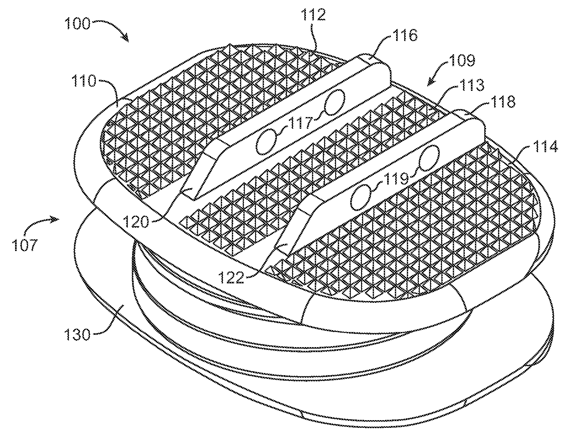
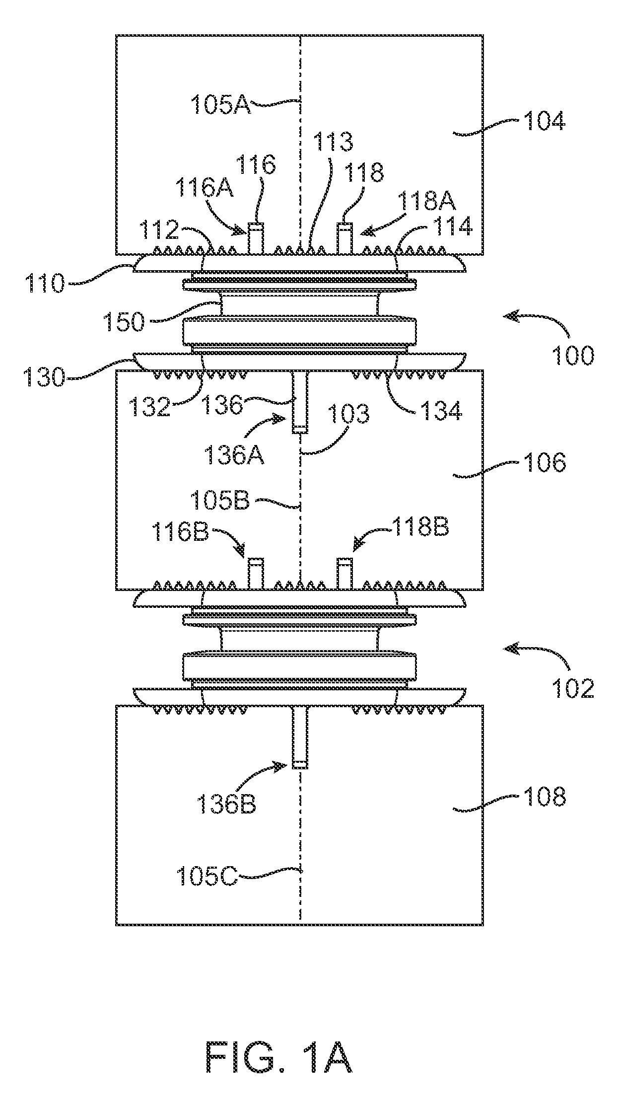
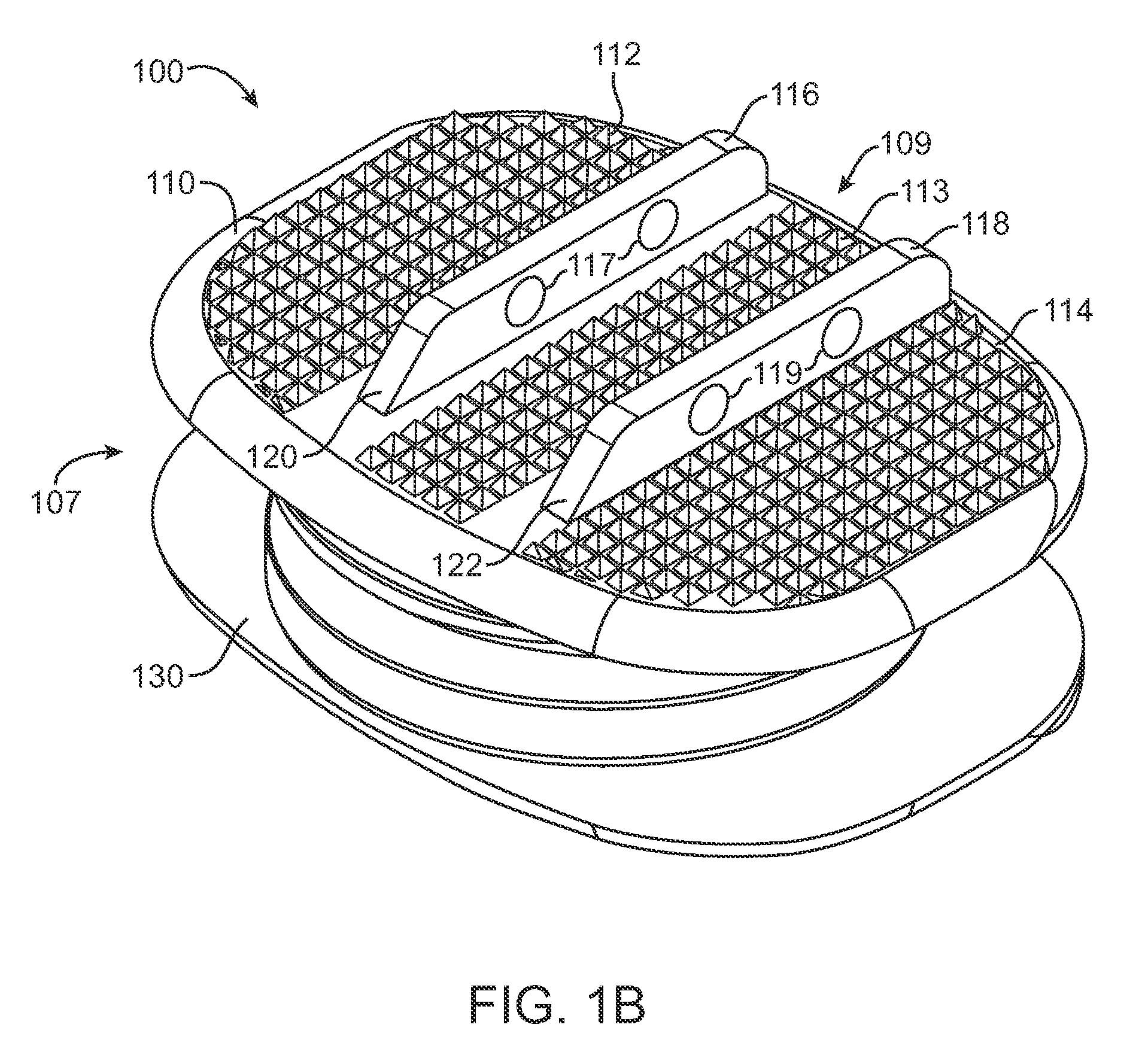
[0030]FIG. 1A shows an intervertebral prosthesis 100 with symmetric offset continuous anchor structures implanted between adjacent vertebrae according to an embodiment of the present invention. An upper vertebra 104, a middle vertebra 106 and a lower vertebra 108 are components of a patient spine and include midlines 105A, 105B and 105C respectively. Upper vertebra 104 and middle vertebra 106 define an intervertebral space where intervertebral prosthesis 100 is located. Intervertebral prosthesis 100 includes a midline 103 that coincides with a midline 105B of middle vertebra 106. Intervertebral prostheses 100 includes an upper component 110 that engages upper vertebra 104 and a lower component 130 that engages middle vertebra 106. Intervertebral prosthesis 100 includes an intermediate member 150, or mobile core, disposed between upper component 110 and lower component 130. Upper component 110, intermediate member 150 and lower component 130 form articulate joint so that relative mot...


PUM


Abstract

An implanted intervertebral prosthesis includes first and second components adapted to attach to a first vertebra and a second vertebra, respectively, that define an intervertebral space. The prosthesis includes a first anchor structure on the first component adapted to enter a grove formed in the first vertebra, and a second anchor structure on the second component adapted to enter a grove formed in the second vertebra. The first anchor structure is offset from the second anchor structure to provide separation of the grooves to preserve vertebral thickness and avoid vertebral splitting. The offset anchor structures can be symmetrically disposed about a midline of the prosthesis or asymmetrically disposed about the midline. In some embodiments, the offset anchor structures comprise elongate anchors shaped as fins or keels. In other embodiments, the offset anchor structures comprise rows of pillars disposed in rows.

Description

CROSS REFERENCE TO RELATED APPLICATIONS [0001] The present non-provisional application claims the benefit under 35 USC 119e of U.S. Appl. No. 60 / 820,769 (attorney docket no. 022031-002000US), entitled “Spinal Prosthesis with Offset Anchors,” filed on Jul. 28, 2006, the full disclosure of which is incorporated herein by reference.BACKGROUND OF THE INVENTION [0002] 1. Field of the Invention [0003] This invention relates to medical devices and methods. More specifically, the invention relates to restoration of spinal motion with a prosthetic disc for intervertebral insertion, such as in the lumbar and cervical spine. [0004] In the event of damage to a lumbar or cervical intervertebral disc, one possible surgical treatment is to replace the damaged disc with an intervertebral disc prosthesis. Several types of intervertebral disc prostheses are currently available. One type available under the trademark SB Charite (DePuy Spine, a division of Johnson & Johnson, New Brunswick, N.J.), inclu...

Claims


Application Information

Patent Timeline
Patent Type & Authority Applications(United States)
IPC IPC(8): A61F2/44A61B17/56
CPCA61F2/442A61F2002/30495A61F2002/30843A61F2002/30884A61F2220/0025A61F2002/30899A61F2002/443A61F2002/449A61F2002/30892
Inventor DE VILLIERS, MALANHOVDA, DAVID
Owner SIMPLIFY MEDICAL PTY LTD
Why Eureka
Try Eureka