Sample transport rack

a technology of sample storage and storage rack, which is applied in the direction of instruments, measurement devices, chemistry apparatus and processes, etc., can solve the problems of short maximum distance between the information storage medium and the read/write mechanism mounted in the apparatus, the permissible reading distance, and the maximum distance allowed between the information storage medium and the read/write mechanism, etc., to achieve the effect of steady transmission of information stored

Inactive Publication Date: 2008-03-13
HITACHI HIGH-TECH CORP
View PDF8 Cites 16 Cited by
  • Summary
  • Abstract
  • Description
  • Claims
  • Application Information

AI Technical Summary

Benefits of technology

[0008]An object of the present invention is to provide a sample transport rack that is capable of steadily transmitting information stored in an RFID tag or another storage medium to an analyzer, sample pretreatment apparatus, or another apparatus when the RFID tag or another storage medium is attached to a sample cup mounted in the sample transport rack.
[0013]The present invention makes it possible to steadily transmit information stored in an RFID tag or another storage medium to an analyzer, sample pretreatment apparatus, or other apparatus when the RFID tag or another storage medium is attached to a sample cup mounted in a sample transport rack.

Problems solved by technology

However, an RFID tag or other information storage medium having an electronic circuit that uses an electromagnetic wave or the like is not suitable for use with the sample cup.
However, when the 13.5 MHz band RFID tag is used, the permissible reading distance, that is, the maximum distance permitted between the information storage medium and a read / write mechanism mounted in the apparatus, is short.
Therefore, when the 13.5 MHz band RFID tag is attached to the lateral surface of a test tube, it is difficult to steadily acquire information because the reading distance varies depending on vibration caused by sample transport rack movement or test tube orientation or other RFID tag mounting condition.
However, when the test tube to which the 13.5 MHz band RFID tag is attached is mounted in a conventional sample transport rack, the information cannot be read because the bottom surface of the test tube is hidden by the sample transport rack.

Method used


Image

  • Sample transport rack
  • Sample transport rack
  • Sample transport rack

Examples


Embodiment Construction

[0018]The configuration of a sample transport rack according to an embodiment of the present invention will now be described with reference to FIGS. 1 to 3.

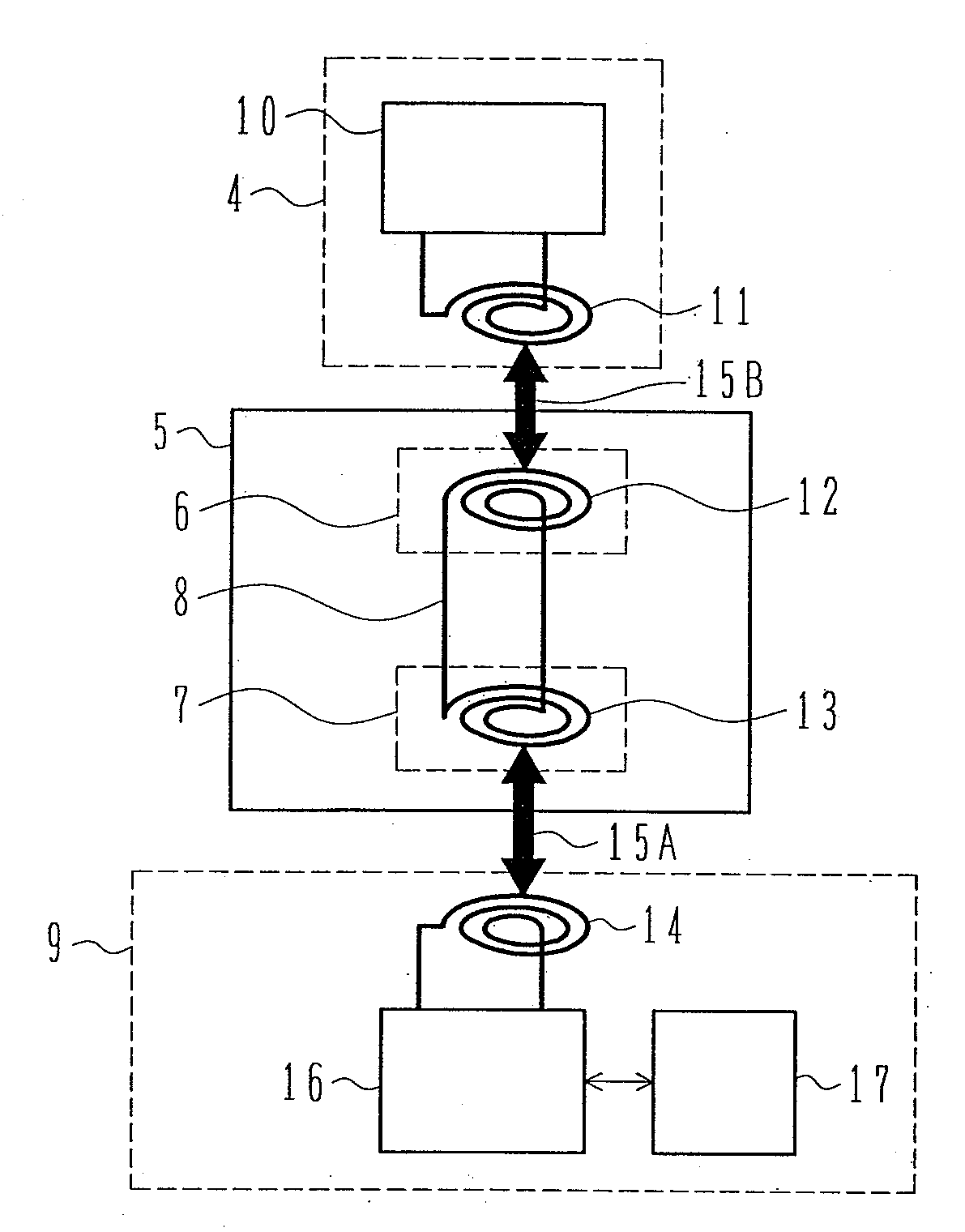
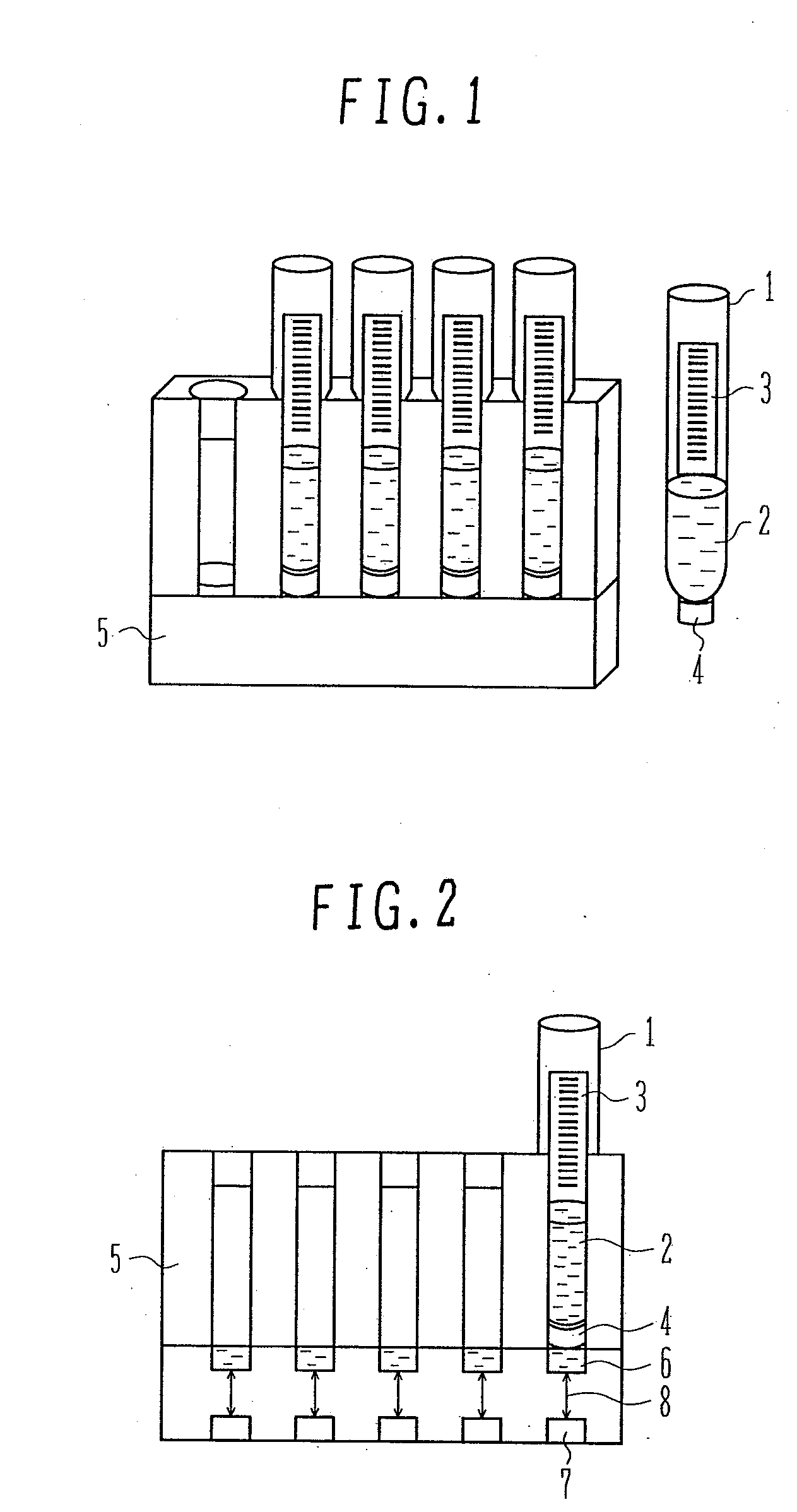
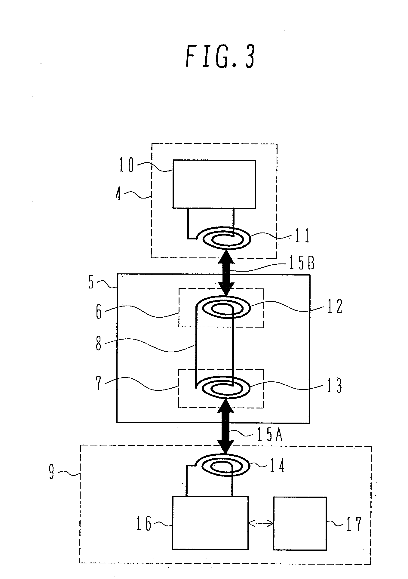
[0019]FIG. 1 is a perspective view illustrating the external configuration of the sample transport rack according to an embodiment of the present invention. FIG. 2 is a perspective view illustrating the internal configuration of the sample transport rack according to an embodiment of the present invention. FIG. 3 is a block diagram illustrating an analysis system that uses the sample transport rack according to an embodiment of the present invention. In FIGS. 1 to 3, like reference numerals represent like elements.

[0020]As shown in FIG. 1, a sample cup 1 is typically a test tube. A microcup and a blood collection tube are also sample cups. A sample 2 is stored inside the sample cup 1. An information storage medium 4, which is typically an RFID tag, is attached to the outer bottom surface of the sample cup 1. The information stora...


PUM

PropertyMeasurementUnit
magnetismaaaaaaaaaa
shapeaaaaaaaaaa
flexibleaaaaaaaaaa

Abstract

The present invention provides a sample transport rack that is capable of steadily transmitting information stored in an RFID tag or another storage medium to an analyzer, sample pretreatment apparatus, or another apparatus when the RFID tag or another storage medium is attached to a sample cup mounted in the sample transport rack. The information stored in an information storage medium attached to the sample cup, which is mounted in the sample transport rack, is transmitted to an automated analyzer that uses the sample transport rack by a storage medium transmission / reception coil of the information storage medium, a sample transmission / reception coil of the sample transport rack, an apparatus transmission / reception coil, and an apparatus side transmission / reception coil of the automated analyzer.

Description

BACKGROUND OF THE INVENTION[0001]1. Field of the Invention[0002]The present invention relates to a sample transport rack that is used to retain a sample cup and move a sample inside an analyzer or sample pretreatment apparatus, between apparatuses, and in a sample transport system.[0003]2. Description of the Related Art[0004]The sample transport rack is generally used to retain a test tube, microcup, blood collection tube, or other sample cup and move a sample and sample cups inside an analyzer or sample pretreatment apparatus, between the analyzer and sample pretreatment apparatus or other device, or in a sample transport system. In the past, a bar code was attached to a lateral surface of the sample cup as means for managing the ID of each stored sample (refer, for instance, to JP-A-2003-294764). In recent years, however, a method for managing the ID or other information about a sample by attaching an RFID tag or other IC-based storage medium to or incorporating it into the sample...

Claims


Application Information

Patent Timeline
Patent Type & Authority Applications(United States)
IPC IPC(8): G01N35/10
CPCB01L9/06B01L2300/022G01N2035/00801G01N35/00732G01N2035/00782B01L2300/023
Inventor WATARI, SHIGENORI
Owner HITACHI HIGH-TECH CORP
Why Eureka
Try Eureka