Tool case

a tool and case technology, applied in the field of tools storage and storage devices, can solve the problems of lack of features which enhance utility, lack of structure, and lack of prior devices, and achieve the effects of reducing gravitational load, facilitating versatile storage capacity and tool display, and reducing structural strength

a tool and case technology, applied in the field of tools storage and storage devices, can solve the problems of lack of features which enhance utility, lack of structure, and lack of prior devices, and achieve the effects of reducing gravitational load, facilitating versatile storage capacity and tool display, and reducing structural strength

US20080067095A1Inactive Publication Date: 2008-03-20ALLTRADE TOOLS

Image

  • Tool case
  • Tool case
  • Tool case

Examples


Embodiment Construction

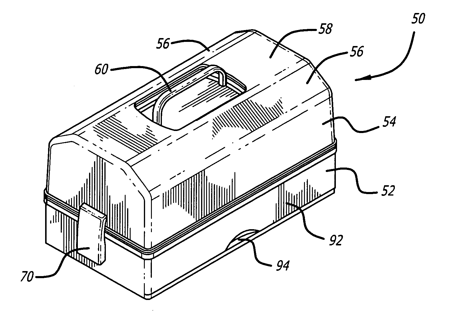
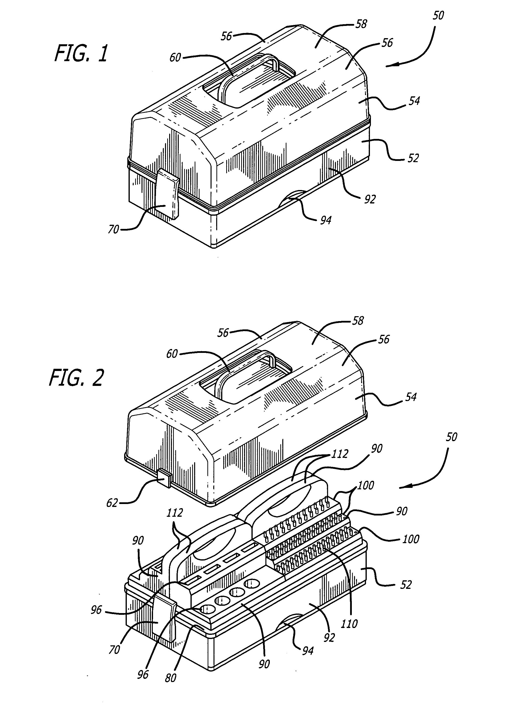
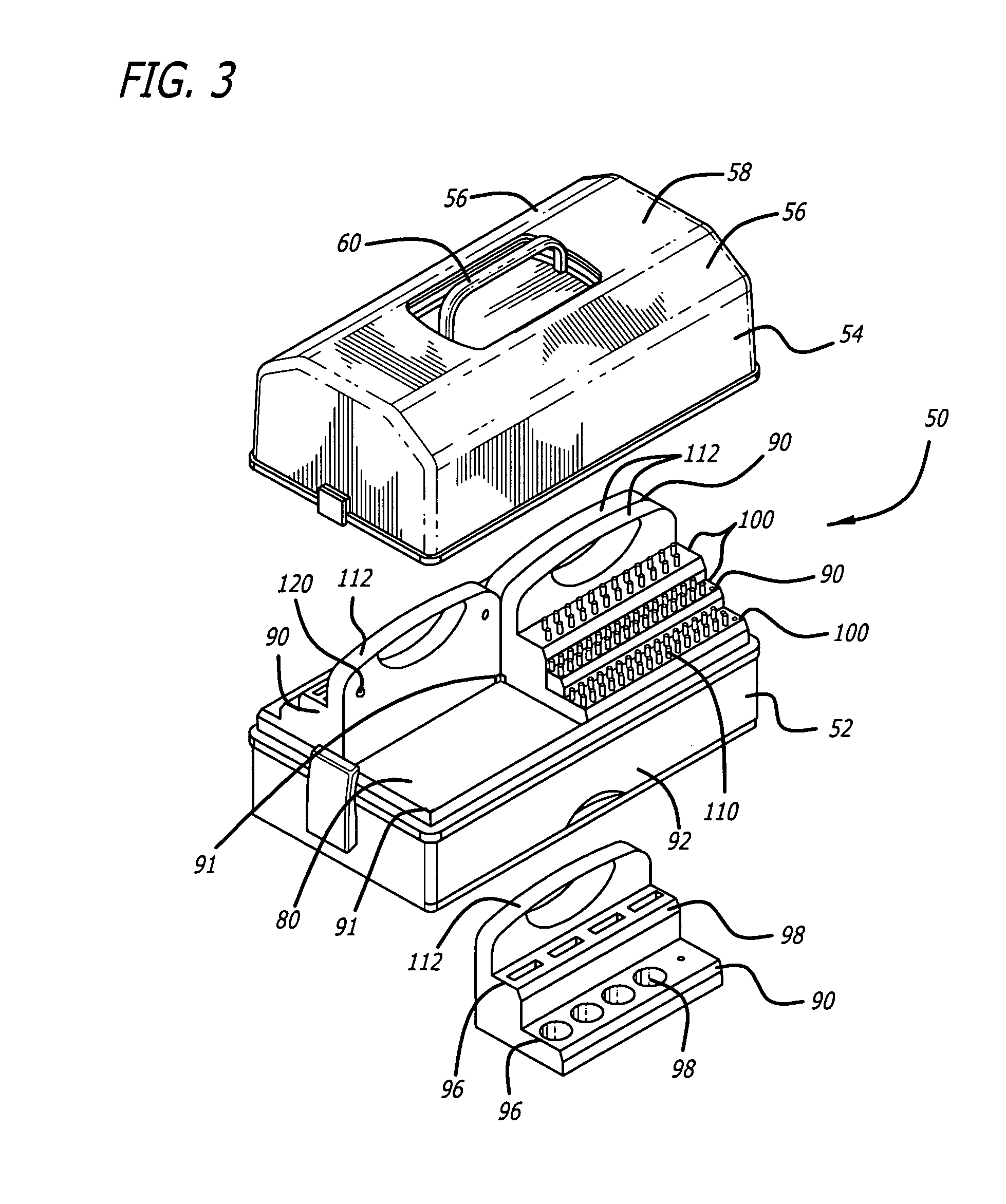
[0027]With reference to the drawings which are provided by way of example and not limitation, there is shown a tool case incorporating various features of the present invention. It is to be understood that a number of different embodiments are contemplated and that one particular embodiment may include all or fewer than all of the features of the present invention. The tool case includes modular components which can be displayed separate from a base and cover of the tool case. The tool case also embodies structure lending itself to conducting a quick inventory of its contents. An additional structural configuration is disclosed which facilitates the use of light weight translucent materials to enable inspection of the interior of the case.

[0028]As shown in FIGS. 1 and 2, in one embodiments the present invention is embodied in a tool case 50 including a base 52 and a cover 54. Although various configurations are contemplated, the tool case 50 is generally rectangular in shape with th...


PUM


Abstract

A tool case including modular storage compartments. In one aspect, the tool case includes a translucent cover and the modular storage compartments can be removed from the tool case and displayed or mounted to a surface. In another aspect, the case may be configured such that the gravitational load of the contents of the case does not flow through the cover when the case is lifted by a handle, thus facilitating the cover to be made from lightweight translucent material. This configuration is achieved by connecting the handle to the floor of the base of the case, allowing the handle to protrude through an opening in the cover, the cover being separately removable.

Description

CROSS-REFERENCES TO RELATED APPLICATIONS[0001]The present application is a continuation-in-part of application Ser. No. 11 / 121,905, filed May 3, 2005, which is incorporated herein entirely by reference.BACKGROUND OF THE INVENTION[0002]The present invention relates to devices for storing and carrying items and more particularly, to a case for receiving and retaining tools.[0003]Tool boxes have been used for many years to store tools, tool parts and fasteners. Tool boxes come in a variety of shapes and sizes and can be portable or fixed structures. Certain tool boxes are designed to hold a particular tool or components thereof. Other devices are configured to store a plurality of different devices.[0004]Generally, tool boxes or cases are designed to maximize storing capacity. Tool boxes sometimes include trays and compartments utilized to retain tools. Typically, the tool box will have a cover configured to protect the tools or to aid in holding the tools in place. With the cover open...

Claims


Application Information

Patent Timeline
20 Mar 2008
Publication
US20080067095A1
IPC
B65D85/28
CPC
B25H3/023
Inventors
MUELLER, GWEN WILLIS