Wheel Bearing Device

a technology of bearings and components, applied in the direction of bearing unit rigid support, couplings, transportation and packaging, etc., can solve the problems of high manufacturing cost, and achieve the effect of reducing cost, cost reduction, and reducing number of parts

Inactive Publication Date: 2008-04-24
HONDA MOTOR CO LTD +1
View PDF8 Cites 14 Cited by
  • Summary
  • Abstract
  • Description
  • Claims
  • Application Information

AI Technical Summary

Problems solved by technology

Since the race machining step is added to the manufacturing process, the manufacturing cost is high.

Method used


Image

  • Wheel Bearing Device
  • Wheel Bearing Device
  • Wheel Bearing Device

Examples


Embodiment Construction

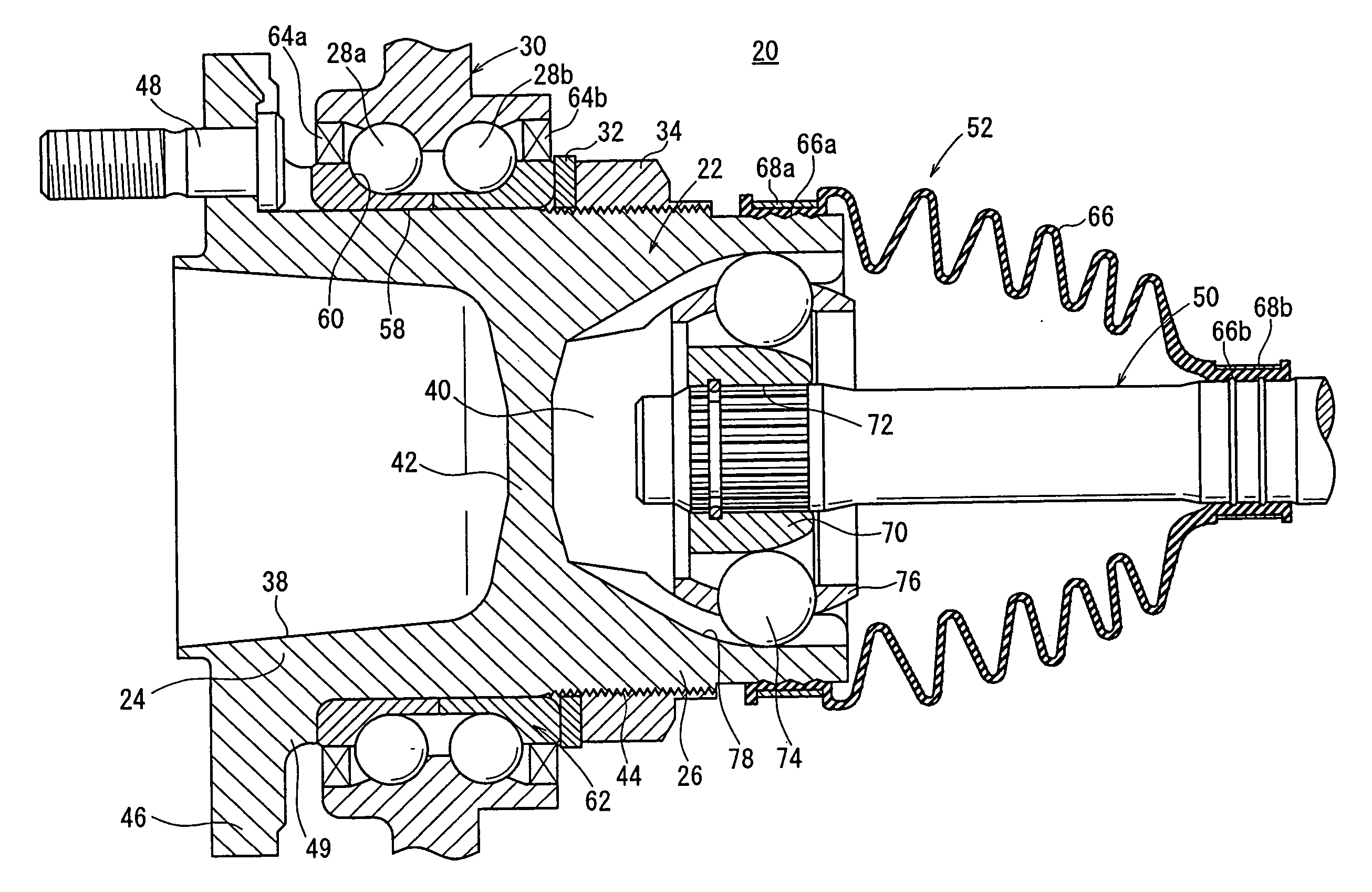
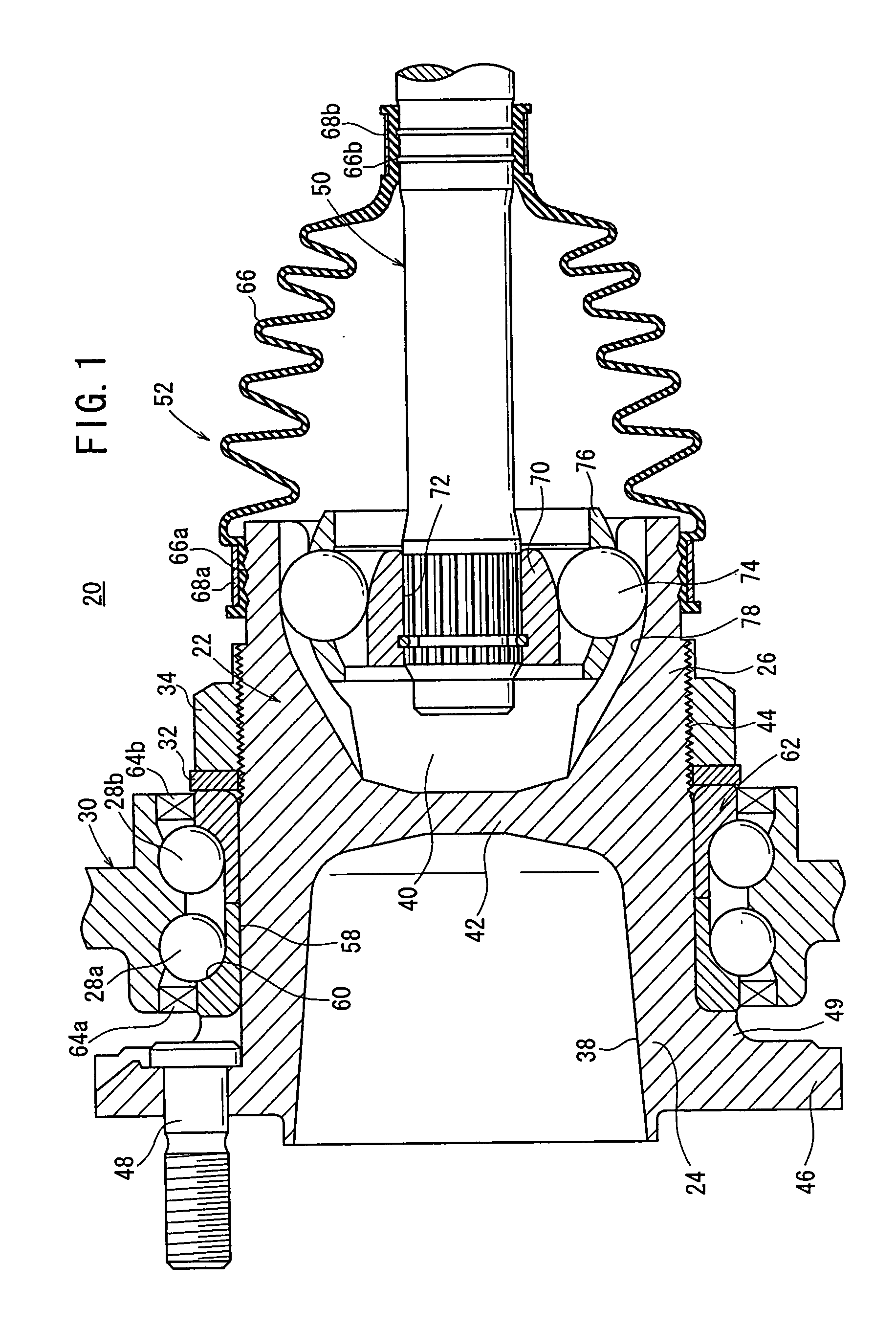
[0022] In FIG. 1, the reference character 20 denotes a wheel bearing device according to an embodiment of the present invention.

[0023] The wheel bearing device 20 has a bearing body 22 comprising a substantially coaxial integral combination of a hub to which an automobile wheel is to be attached and an outer race member of a constant velocity universal joint. The bearing body 22 comprises a hub portion 24 as the hub and an outer race portion 26 as the outer race member.

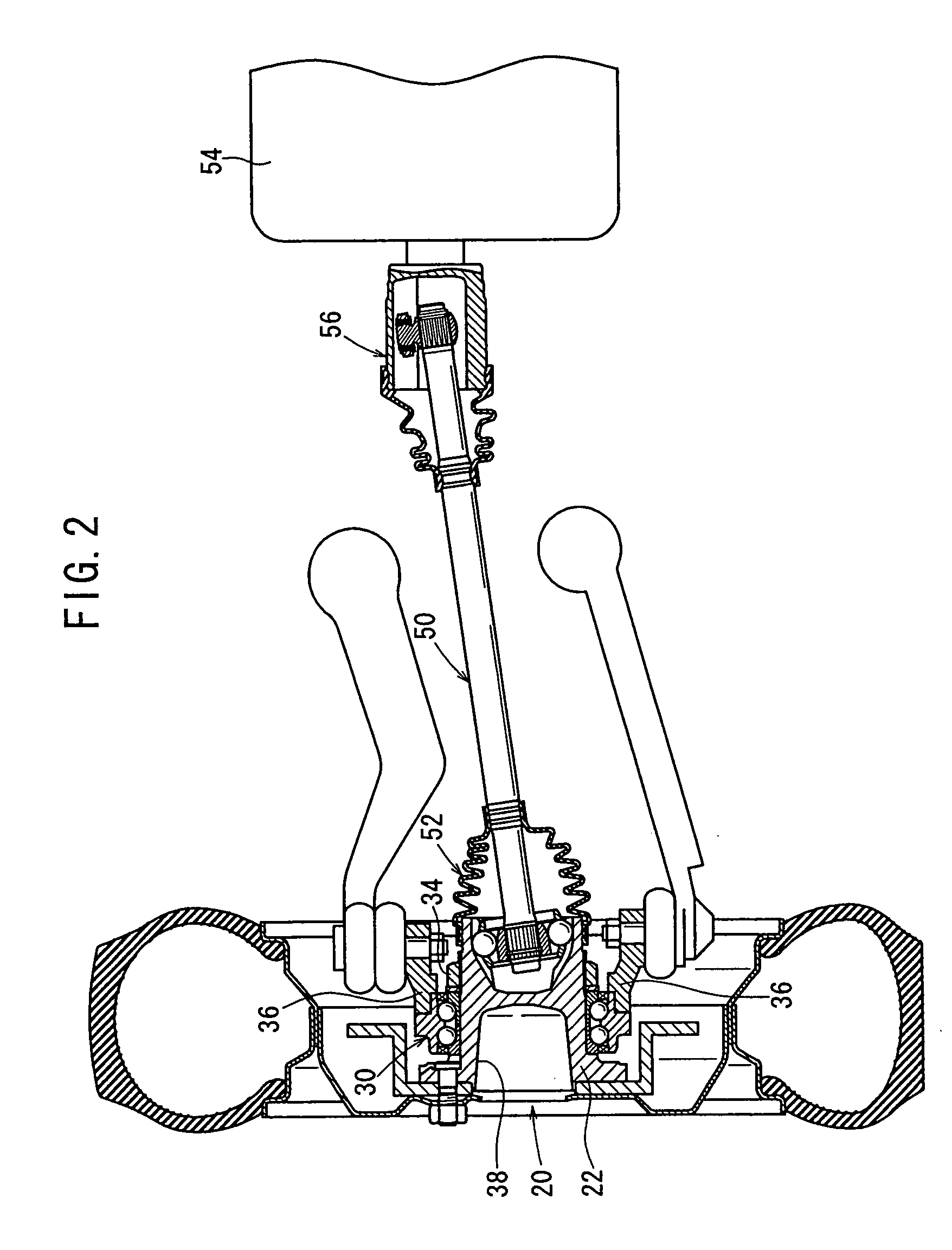
[0024] The wheel bearing device 20 also has a hub bearing 30 fitted over an outer circumferential surface of the bearing body 22 and having rolling bodies 28a, 28b comprising a plurality of steel balls rollingly held by a retainer, not shown, a ring-shaped washer 32 and a nut (tightening mechanism) 34 which are fitted over the outer circumferential surface of the bearing body 22 and fixing the bearing body 22 to the hub bearing 30, and a knuckle 36 (see FIG. 2) disposed on an outer circumferential surface of the hub...


PUM


Abstract

A wheel bearing device, includes a cylindrical bearing body having a wheel side hub part and a constant velocity joint outer ring part which are formed integrally with each other, a hub bearing having an externally fitted member fitted onto the bearing body and rolling elements, and a nut member fixing the bearing body to the hub bearing supported on a vehicle body side by tightening it to the screw part of the bearing body after the bearing body is press-fitted into the through-hole of the externally fitted member from the wheel side.

Description

TECHNICAL FIELD [0001] The present invention relates to a wheel bearing device which is capable of supporting a wheel rotatably on a vehicle. BACKGROUND ART [0002] Power transmitting systems for transmitting rotational drive power from the engine of an automobile to the drive wheels thereof are required to address angular and axial displacements due to a change in the relative positional relationship between the engine and the wheels. As shown in FIG. 8, for example, there has been employed a structure wherein a drive shaft 1 is interposed between an engine and a drive wheel, and has an end connected to a differential mechanism 3 by a sliding-type first constant velocity universal joint 2 and the other end to a drive wheel 5 by a fixed-type second constant velocity universal joint 4 (see Japanese Laid-Open Patent Publication No. 2000-135903). [0003] The sliding-type first constant velocity universal joint 2 can absorb axial displacements by so-called plunging, and the fixed-type sec...

Claims


Application Information

Patent Timeline
Patent Type & Authority Applications(United States)
IPC IPC(8): F16D3/22
CPCB60B3/04B60B27/00B60B27/0005F16C2326/02B60B35/14F16C19/185F16C35/063B60B27/0042F16C2226/60
Inventor MABUCHI, TORUKUDO, SATORU
Owner HONDA MOTOR CO LTD
Why Eureka
Try Eureka