Quick release axle assembly

a technology of axle and wrench, which is applied in the direction of axle suspension, release mechanism, cycle equipment, etc., can solve the problems of weak tubular body strength, time and effort needed for mounting and dismantling of the tubular body, and not only a wrench, so as to achieve the effect of simple installation and disassembly and improve the strength of installation

Inactive Publication Date: 2010-06-15
SAKAE ENG
View PDF2 Cites 16 Cited by
  • Summary
  • Abstract
  • Description
  • Claims
  • Application Information

AI Technical Summary

Benefits of technology

[0017]According to the present invention, because the holding member with collet shape contacts to the wall surface of the penetrating hole of the shaft mounting portion and shrinks diameter, the tubular body and the holding member can be directly inserted into the penetrating hole. In addition, through shrinking diameter of the holding member with collet shape by a moving operation of the diameter shrinking means, the tubular body can be taken off from the penetrating holes. Therefore, it is possible to perform the installing and dismantling works simply. In addition, according to the present invention, because the pair of shaft mounting portions are nipped and held by two holding members without designing slotted fingers on the tubular body, the strength of installation is improved.

Problems solved by technology

However, as stated above, when screwing the holding member or performing the tightening of the fastening bolt, there is a problem that not only is a wrench needed, but also time and exertion are needed for mounting and dismantling of the tubular body.
However, since there are slotted fingers at both ends of the tubular body, there is a drawback that the strength of the tubular body becomes weak.

Method used


Image

  • Quick release axle assembly
  • Quick release axle assembly
  • Quick release axle assembly

Examples


embodiment

[0025]Embodiments of the invention will be described in detail hereinbelow with reference to the drawings.

[0026]FIG. 6 is an oblique view of a fork structure with an axle assembly 10 related to the present invention being installed.

[0027]In FIG. 6, 1 shows front fork. On the front fork 1, a suspension fork 2 with a reverse U-shape is installed. On lower portions of respective forks of the suspension fork 2, shaft mounting portions 3A and 3B are mounted. On the shaft mounting portions 3A and 3B, a penetrating hole 4 is respectively formed. An axle assembly 10 is passed through the penetrating hole 4 of the shaft mounting portion 3A on one side and is inserted into and passed through hub 5. Further, the axle assembly is passed though the penetrating hole 4 of the shaft mounting portion 3B on the other side.

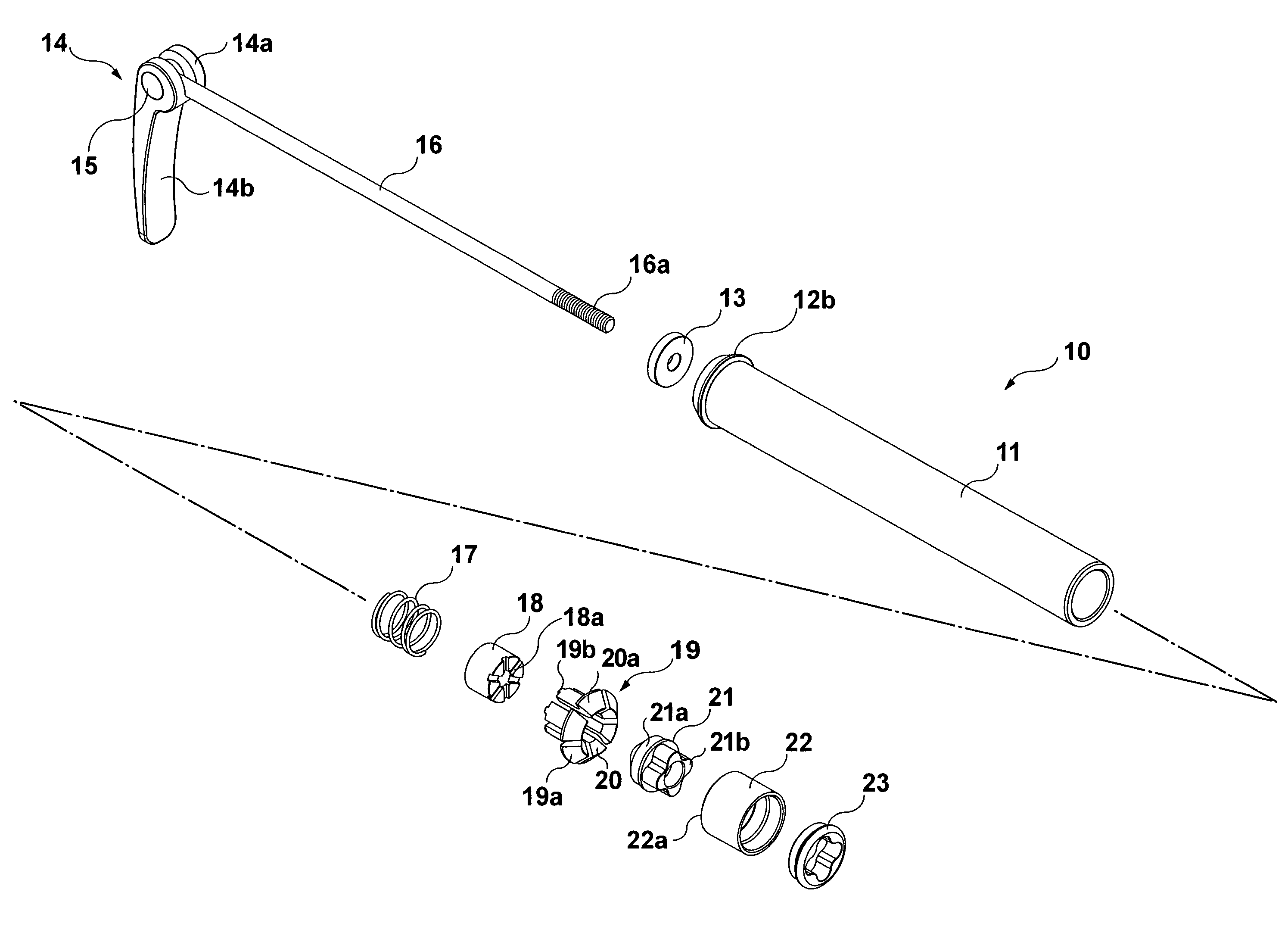
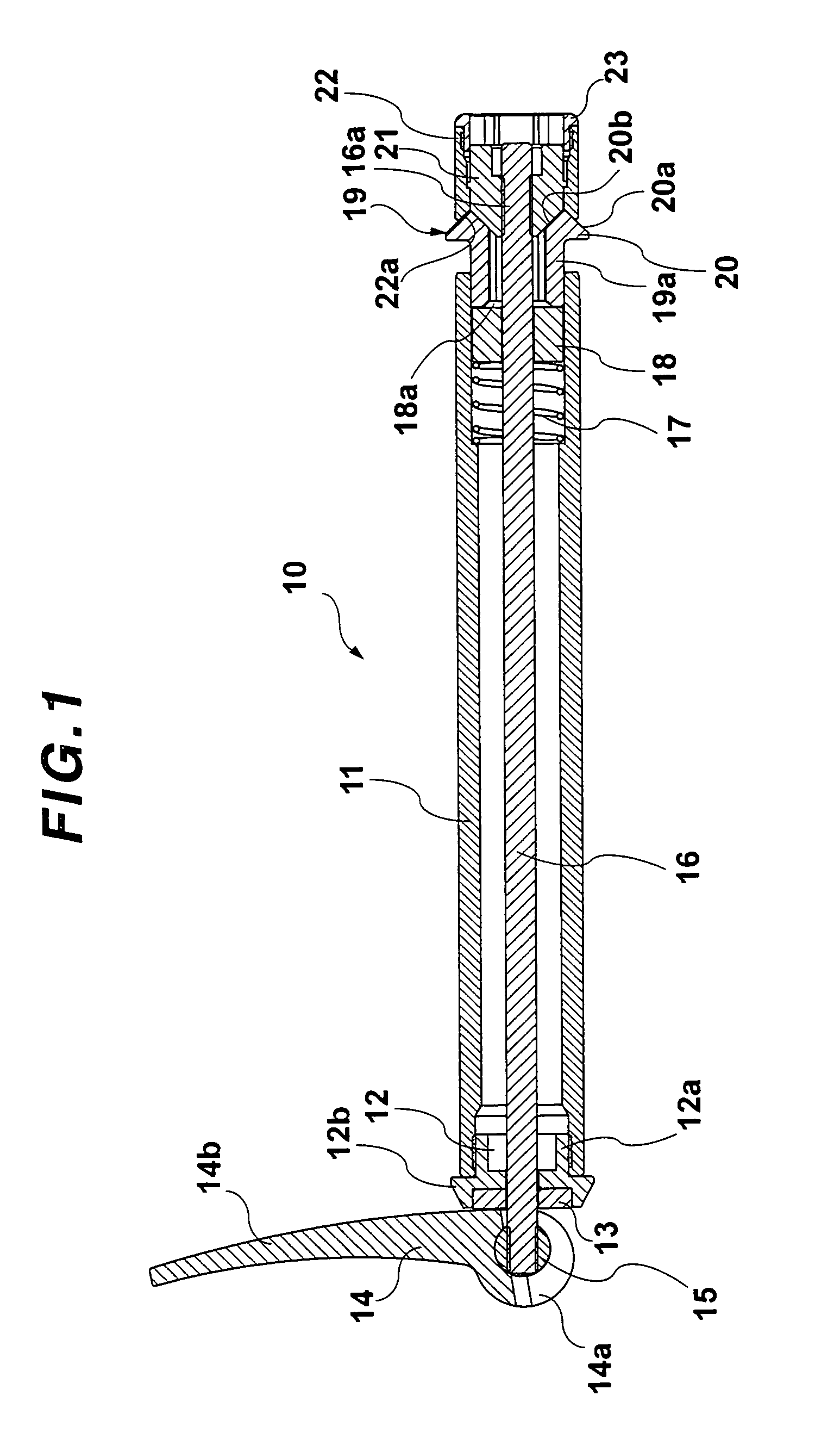
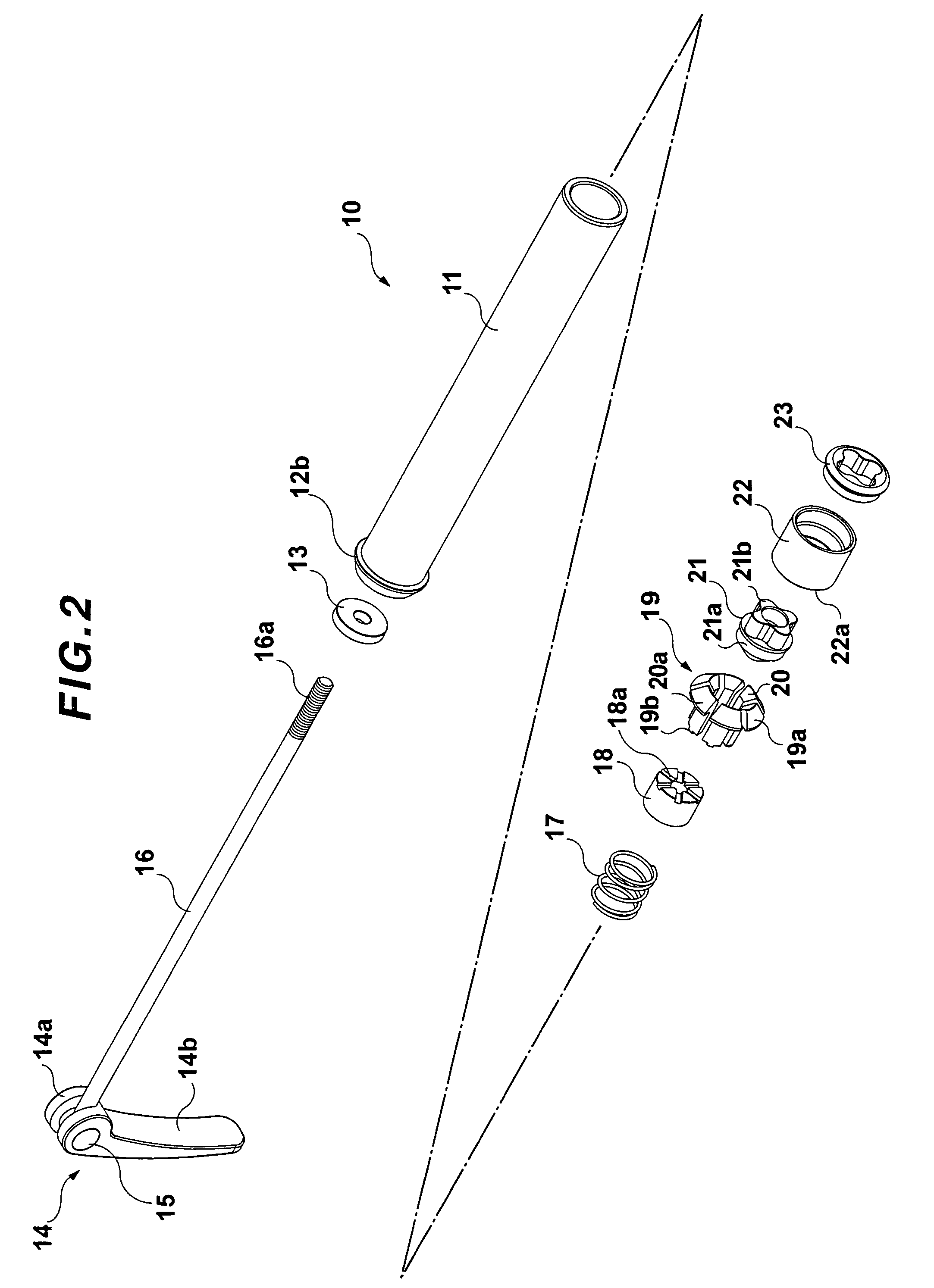
[0028]FIG. 1 is a sectional view of the axle assembly 10 in the present invention, and FIG. 2 is a disassembled oblique view of the axle assembly 10.

[0029]The axle assembly 10 has a...


PUM


Abstract

An axle assembly includes a first holding member, and a second holding member with a collet shape on a tubular body. The second holding member is inserted into a penetrating hole of a shaft mounting portion so as to reduce its diameter. The tubular body is directly inserted into the penetrating hole. When moving the fastening bar by operation of the cam lever, both holding members nip and hold the shaft mounting portion. While dismantling, a diameter shrinking part moves so as to reduce a diameter of the second holding member.

Description

BACKGROUND OF THE INVENTION[0001]1. Field of the Invention[0002]The present invention relates to an axle assembly to mount a wheel hub of a bicycle to a front fork or a suspension fork.[0003]2. Related Background Art[0004]A conventional axle assembly has a tubular body and a pair of holding members with a flange shape. In the conventional axle assembly, both ends of the tubular body are inserted into respective penetrating holes of a pair of shaft mounting portions (i.e. dropouts) furnished below a suspension fork; the respective holding members are screwed into both ends of the tubular body; and the holding members are used to nip and hold the pair of shaft mounting portions. The tubular body is thus installed on the pair of the shaft mounting portions. The tubular body rotatably supports a hub of a wheel.[0005]The shaft mounting portions to mount such a conventional axle assembly are formed into two separate structures in order to enable the diameter of the penetrating holes of th...

Claims


Application Information

Patent Timeline
Patent Type & Authority Patents(United States)
IPC IPC(8): B60B37/00
CPCB62K25/02B62K2206/00
Inventor CHONAN, YOSHIYA
Owner SAKAE ENG
Why Eureka
Try Eureka