Eureka AIR delivers breakthrough ideas for toughest innovation challenges, trusted by R&D personnel around the world.

Scaleless on-line rheometer device

a rheometer and scaleless technology, applied in the direction of instruments, manufacturing tools, volume/mass flow by differential pressure, etc., can solve the problems of inability of the components of known rheometers, such as gear pumps, stress transducers, sensors and other moving parts, to withstand the wear caused by abrasive fillers

Inactive Publication Date: 2002-06-18
SABIC INNOVATIVE PLASTICS IP BV
View PDF17 Cites 17 Cited by
  • Summary
  • Abstract
  • Description
  • Claims
  • Application Information

AI Technical Summary

Benefits of technology

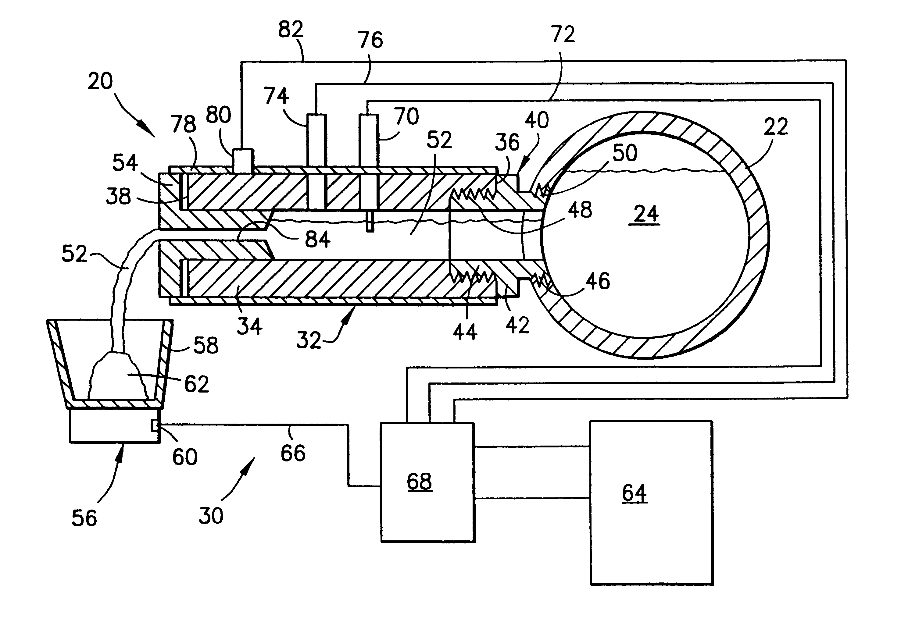
The conduit containing a main stream of the polymer melt, or possibly he die head may be modified by drilling a small hole, perhaps 0.5 inch in diameter, into the conduit to tap into the main stream thereby forming a side stream, then adding a barrel extension to the side stream with a capillary orifice threaded in or mounted at its exit. The rheometer barrel that is extended out of the die head is wrapped with a heater jacket to prevent heat loss or gain. A very small fraction of the polymer melt is diverted to the rheometer barrel and the capillary. The air-cooled plastic is then discharged. The response of the rheometer is minutes after making setpoint adjustment. To lengthen the interval required to empty the receptacle, the receptacle may be rotated, or a grinder / pelletizer may be used, or both.
The rheometer just described, unlike commercially available options, does not require that the pressure and temperature in the die head and in the capillary be controlled. The algorithm to calculate real tic viscosity, from P, T, and MR, is unique and the constants used in the algorithm are characteristics of the product and thus referred to as signatures. The rheometer's capillary orifice enables "apples to apples" comparison with quality assurance data since the melt viscosity rheometers used in the quality assurance laboratory are based on capillary geometry (for example, a melt flow indexer described in ASTM D1238). The elimination of the gear pump also greatly increases the flexibility and durability of the rheometer of the invention.
The present invention has several features and provides a number of advantages, some of which are summarized as follows: it enables truly on-line measurements for attaining quicker response and more accurate control of manufacturing processes involving polymer melts; mounts easily to a large variety of polymer processors such as single and twin screw extruders as well as any other continuous mixers and kneaders; permits the conduct of on-line measurements with a minimal intrusion and no contamination of the main process stream being monitored; permits increased versatility in the nature and extent of the information derived from on-line measurements of polymer melts, as well as increased accuracy in the information itself; enables ease of installation and use in connection with current manufacturing equipment and techniques; allows ready adaptation for use in connection with a wide variety of materials and operating conditions; provides a convenient station for additional sensing and observation devices available for monitoring the quality of the polymer melt and integration with manufacturing processes via feedback loop controller facilitates cleaning and general maintenance, as well as replacement of component parts either for repair or adaptation to specific materials and operating conditions; and provides a simple and rugged construction without moving parts for economical manufacture and reliable long term service. This data may be used as an input for the determination of the viscosity on a continuous basis. An advantage of this technique is a reduction in weight variability which might occur when using the stationary receptacle.

Problems solved by technology

Previously, commercially available in / on line rheometer can not meet the expectations recited in (a) and (b) above.
The difficulties lay with the inability of the components in known rheometers, such as gear pumps, stress transducers, sensors and other moving parts to withstand the wear caused by abrasive fillers such as glass fibers and minerals.

Method used


Image

  • Scaleless on-line rheometer device
  • Scaleless on-line rheometer device
  • Scaleless on-line rheometer device

Examples


Embodiment Construction

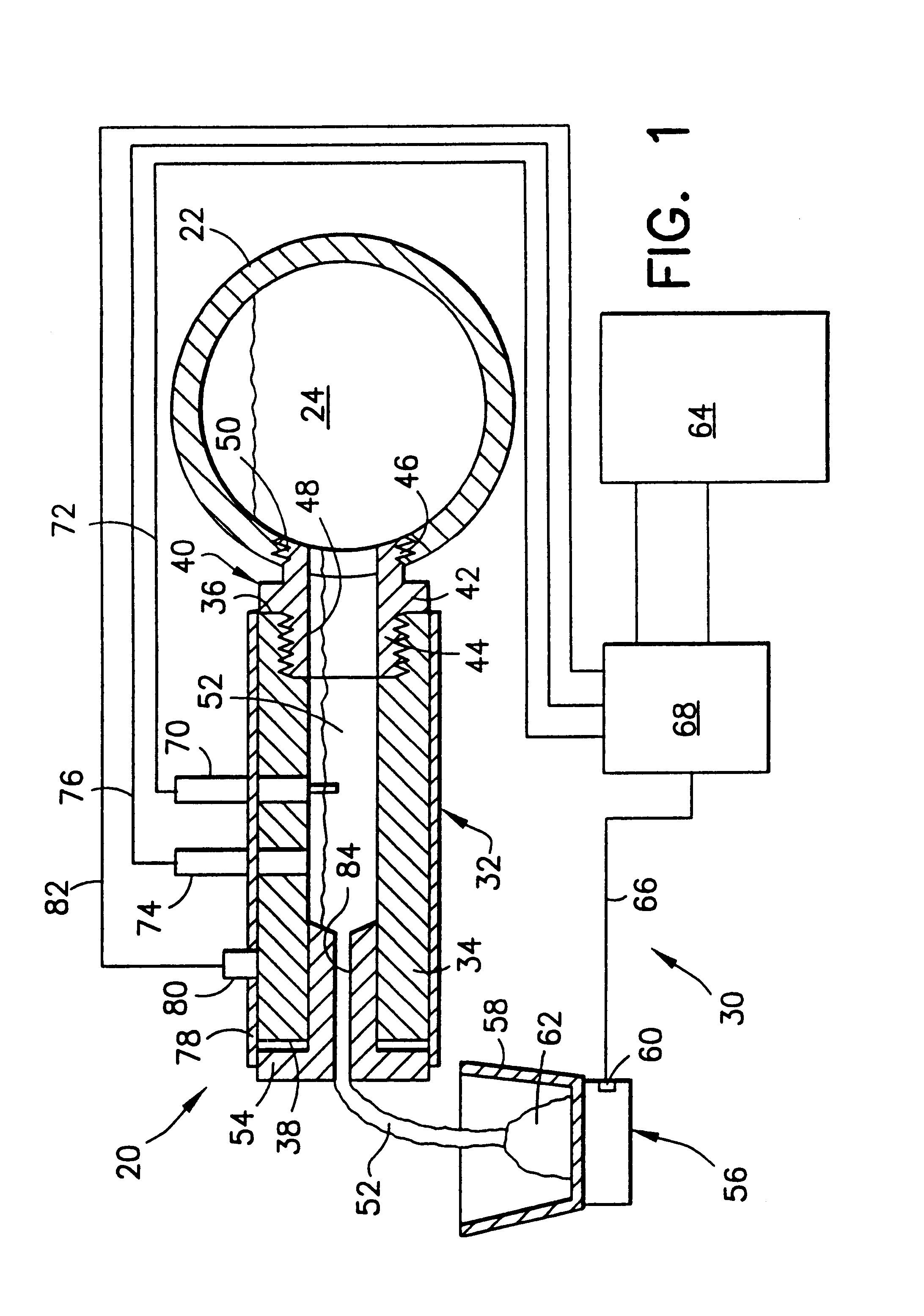
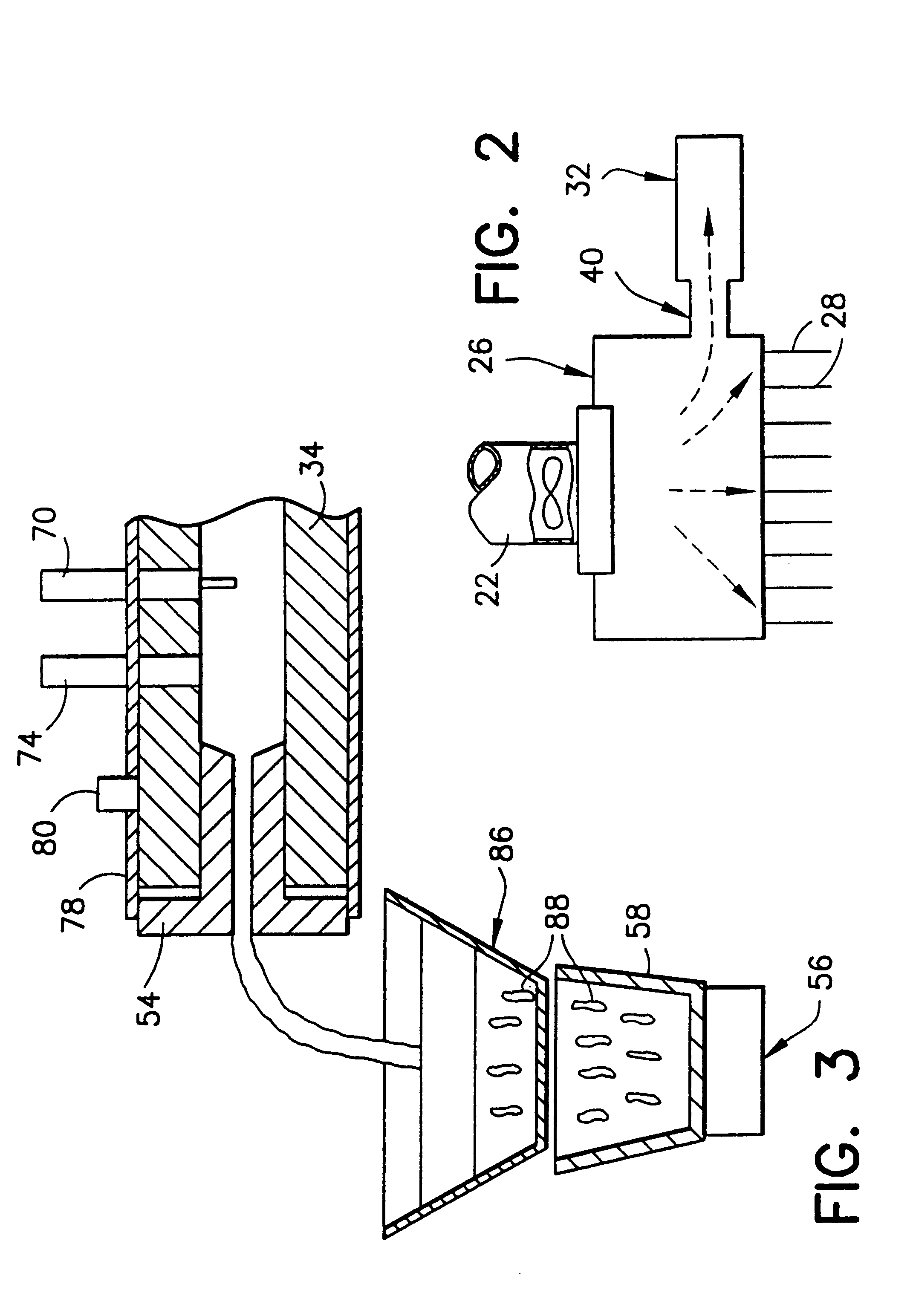
Turn now to the drawings and, initially, to FIG. 1 which diagrammatically illustrates part of a plastics extrusion machine 20 including a conduit 22 containing a main stream 24 of polymer melt terminating at a die head 26 (FIG. 2) of a polymer extruder which produces a plurality of polymer strands 28. The plastics extrusion machine 22 includes a system 30 for providing process control information concerning the polymer melt.

In turn, the system 30 includes an on-line rheometer device 32 which, in one instance, may be operably attached to the conduit 22 (FIG. 1) or, in another instance, may be operably attached to the die head 26 itself (FIG. 2). In either instance, a barrel member 34 extends between an inlet end 36 and an outlet end 38. The barrel member is selectively attached to the conduit 22 (or to the die head 26) by means of a suitable fitting 40 such as one, for example, which has a central peripheral flange 42 separating an outer threaded nipple 44 from an inner threaded nipp...


PUM

PropertyMeasurementUnit
Pressureaaaaaaaaaa
Diameteraaaaaaaaaa
Diameteraaaaaaaaaa

Abstract

A system for providing process control information, such as viscosity, concerning a polymer melt comprises a means containing a polymer melt under pressure; means for diverting a stream of the polymer melt directly from said containing means to and through an orifice of predetermined geometrical shape wherein the flow of said diverted portion to and through said orifice is unobstructed and directly dependent on the pressure of said main polymer melt wherein the cross sectional area is sized to permit the flow of said diverted melt polymer therethrough absence additional independent means acting on said diverted melt polymer for increasing flow through said orifice; temperature sensing means for measuring the temperature of the diverted melt stream and producing a resultant temperature signal; pressure sensing means for measuring the pressure of the diverted melt stream and producing a resultant pressure signal, said pressure signal being directly dependent on the pressure of polymer in said main polymer melt and the predetermined size of said orifice; means measuring or calculating the production rate of the extruder; and manufacturing control system means responsive to the temperature, pressure and production rate signals for determining process characteristics of the main polymer melt.

Description

1. Field of the InventionThe present invention relates generally to the measurement of process characteristics of melted materials and pertains, more specifically, to the on-line measurement of such characteristics as the viscosity of polymer melts for purposes of monitoring and controlling of manufacturing processes involving molten plastics.2. Description of the Prior ArtRheological testing equipment has been available for a very long time in conducting laboratory measurements of certain important characteristics of polymer melts used in various manufacturing processes. Thus, such properties as viscosity and melt flow index are being measured in the laboratory with increasing accuracy. More recently, efforts have been directed toward the measurement of these characteristics on-line, during the manufacturing process itself, in order to provide constant, closer control over the quality of the melt utilized in the process. On-line measurement requires equipment which not only is rela...

Claims


Application Information

Patent Timeline
IPC IPC(8): G01N11/00G01N11/08G01N33/44B29C48/92G01D21/02
CPCB29C47/0011G01N11/08B29C47/92G01N33/442B29C2947/92019B29C2947/92104B29C2947/9218B29C2947/9219B29C2947/922B29C2947/92209B29C2947/9238B29C2947/9239B29C2947/924B29C2947/92409B29C2947/92485B29C2947/92514B29C2947/926B29C2947/92695B29C2947/92704B29C48/92B29C2948/92209B29C2948/924B29C2948/92409B29C2948/92704B29C48/04B29C2948/92019B29C2948/92104B29C2948/9218B29C2948/9219B29C2948/922B29C2948/9238B29C2948/9239B29C2948/92485B29C2948/92514B29C2948/926B29C2948/92695G01F1/42G01N2035/00227
Inventor TJAHJADI, MAHARIJANSSEN, JOSEPH M. H.FISCHER, GEORGE F.LIN, YE-GANGTADROS, SAFWAT E.GEORGIEVA, GALINA D.HARABURDA, SCOTT S.
Owner SABIC INNOVATIVE PLASTICS IP BV
Why Eureka
Eureka Blog
Learn More