Method for natural gas production

a technology of methane hydrate and natural gas, which is applied in the direction of fluid removal, borehole/well accessories, construction, etc., can solve the problems of not being able to recover methane economically from dissociated methane hydrate, high heat loss, and consumption of all the heating value of recovered methane, etc., to achieve energy efficiency and increase energy efficiency of such effects

Active Publication Date: 2005-01-27
PRECISION COMBUSTION
View PDF7 Cites 27 Cited by
  • Summary
  • Abstract
  • Description
  • Claims
  • Application Information

AI Technical Summary

Benefits of technology

[0010] The present invention is a method and system for dissociating methane hydrate deposits by downhole production of a heated fluid. The method comprises injecting combustion products containing carbon dioxide into a methane hydrate deposit whereby at least a portion of the deposit may be heated to the temperature at which methane hydrate decomposes at the prevailing pressure. By combustion of a carbonaceous fuel downhole, the heat losses involved in piping a heated fluid downhole are avoided. Further, because the combustion products contain carbon dioxide, a hydrate forming gas, at least a portion of the heat required for methane hydrate decomposition can be supplied by the heat of formation of carbon dioxide hydrates. This works because at a given pressure, carbon dioxide hydrate formation can occur at a slightly higher temperature than that for methane hydrate dissociation. By combining downhole combustion with carbon dioxide displacement of methane, the process energy required is significantly reduced. In the method of the present invention, carbon dioxide rich combustion products provide the heat necessary to heat the deposit to a temperature above the methane hydrate decomposition temperature but below the carbon dioxide hydrate formation temperature. Thus, carbon dioxide hydrate formation is enhanced and provides its heat of formation to supply at least a portion of the decomposition heat required for methane hydrate decomposition.
[0011] The ability to generate heat for methane hydrate dissociation downhole resolves the problem that has limited surface heat generation for transport downhole, namely, heat losses completely or almost completely consuming all of the energy value of the methane produced. Methane dissociation from the hydrate itself according to the present invention only requires approximately 10% of the energy content of the released methane. The present invention eliminates the transport heat losses primarily because the heated fluid is produced adjacent to the methane hydrate deposit.
[0012] Although it is often feasible and cost effective to use flame combustion, catalytic combustion provides a method for stabilizing combustion. Catalytic combustion offers the ability to operate without soot formation, even at stoichiometric ratios without excess oxygen. Further, the ability of catalytic combustion to operate across a wide flammability range simplifies control for a downhole hydrate heating system.
[0014] The method of the present invention and a device corresponding thereto offer an energy efficient means of dissociating methane hydrate. One embodiment of the present invention comprising providing the energy released by CO2 hydrate formation offers increased energy efficiency of such a means and system.

Problems solved by technology

Unfortunately, it has not yet been demonstrated that methane can be recovered from dissociated methane hydrates economically.
However, it has been found that pumping a heated fluid from the surface to the methane hydrate deposit results in such high heat loss from transporting the heated fluid downhole that essentially all of the heating value of the recovered methane is consumed to supply the needed energy expended in the recovery process.
In-situ combustion would minimize such transit heat losses but would be difficult to establish in a hydrate bed and would result in undesirably high bed temperatures.
Such a mining system has yet to be demonstrated to be economically feasible.
However, this method has not been demonstrated as feasible as the reaction is slow at the deposit temperatures.

Method used


Image

  • Method for natural gas production
  • Method for natural gas production

Examples


Embodiment Construction

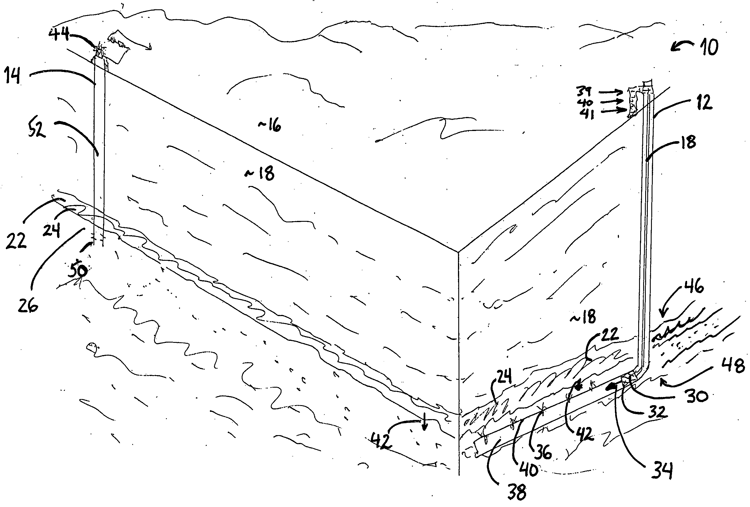
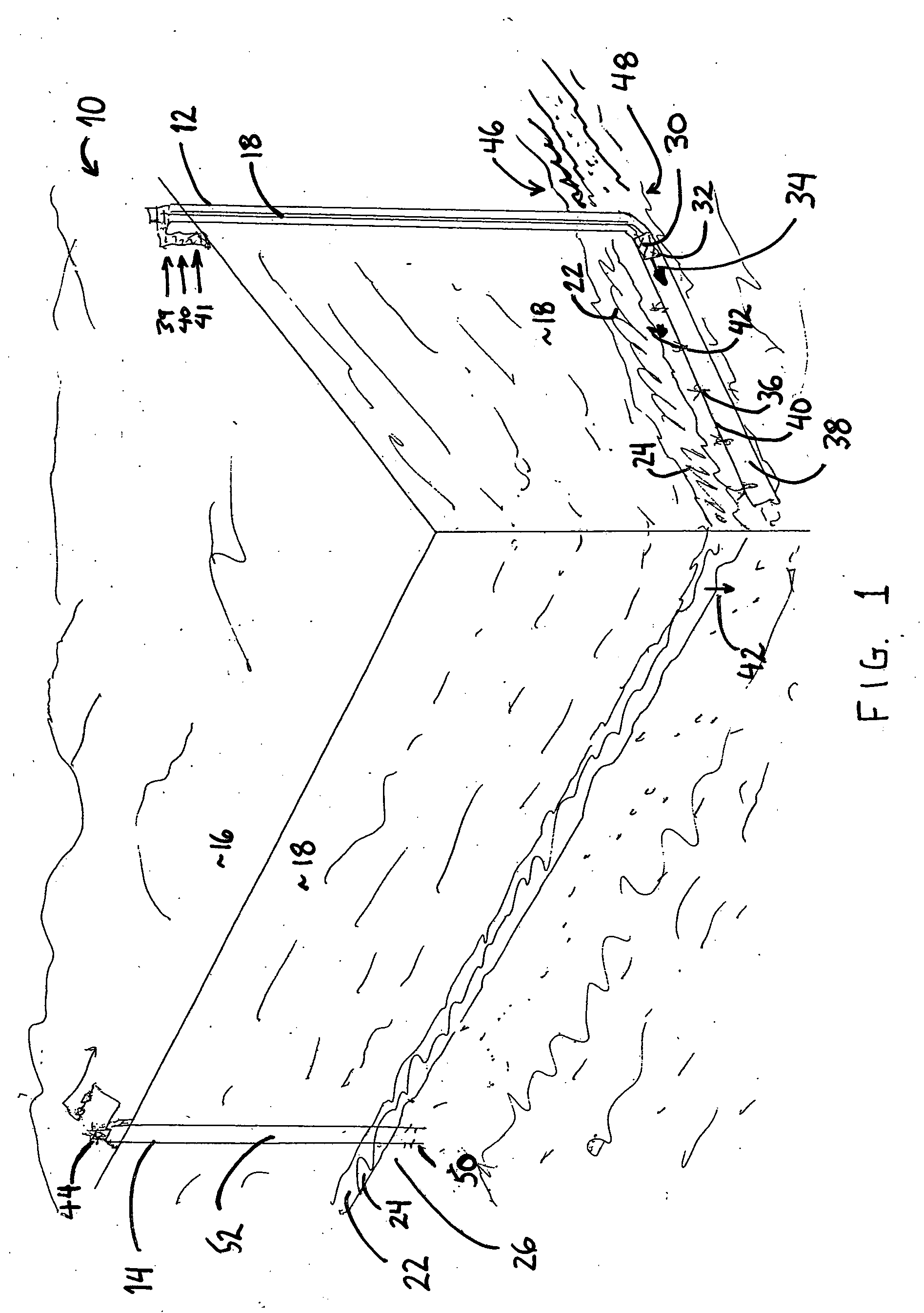
[0016] As depicted in FIG. 1, a methane production system 10 according to the present invention comprises an injection well 12 and a production well 14. Injection well 12 and production well 14 are representative wellbores well known to one skilled in the oil and gas extraction art. Typically, the wellbores extend substantially downward from a point of access, for example, the surface 16 of a stratum 18. The wellbores also may extend substantially downward from the surface of a body of water, sediment deposit, permafrost, or other geological formation. In FIG. 1, injection well 12 and a production well 14 extend downward through stratum 18, through a hydrate formation bed 22 containing methane hydrates 24, and downward from hydrate formation bed 22 into a gas layer 26. As depicted in FIG. 1, injection well 12 is oriented substantially vertical extending downward through hydrate formation bed 22, and transitions to a substantially horizontal orientation 38 passing beneath and proxima...


PUM


Abstract

The present invention is a method and system for dissociating methane hydrate deposits in-situ. An oxidizer fluid and a supply of fuel, both at a pressure higher than that of the methane hydrate deposit, are supplied and delivered to the methane hydrate deposit. The fuel is combusted downhole by reacting it with the oxidizer fluid to provide combustion products. The combustion products are placed in contact with a diluent fluid to produce a heated product fluid. The heated product fluid is injected into the methane hydrate deposit whereby methane is dissociated from the methane hydrate and made available for extraction. In addition, carbon dioxide may be made available to promote the formation of carbon dioxide hydrates from the liberated methane hydrate water.

Description

CROSS-REFERENCE TO RELATED APPLICATION [0001] This application claims the benefit of U.S. Provisional Application No. 60 / 489,876 filed Jul. 22, 2003.BACKGROUND OF THE INVENTION [0002] 1. Field of the Invention [0003] The present invention relates to a method for the production of natural gas from methane hydrate deposits. More particularly, the present invention is directed to the release of methane from methane hydrates. [0004] 2. Description of the Related Art [0005] Methane hydrate deposits are abundant throughout the world and have been estimated to represent by far the greater portion of the world's fossil energy reserve. Within the United States alone, methane hydrates represent an estimated 200,000 Trillion cubic feet (Tcf) of the total 227,500 Tcf of known natural gas reserves. The methane hydrate deposits, occurring at great depths primarily in the oceans, dwarf the total known combined oil and non-hydrate gas reserves. With the United States largely dependent upon imported...

Claims


Application Information

Patent Timeline
Patent Type & Authority Applications(United States)
IPC IPC(8): E21B43/24
CPCE21B41/0064Y02C10/14E21B2043/0115E21B43/243E21B41/0099Y02C20/40
Inventor PFEFFERLE, WILLIAM C.
Owner PRECISION COMBUSTION
Why Eureka
Try Eureka