Valve-driving system of internal combustion engine

a technology of internal combustion engine and valve drive, which is applied in the direction of valve drive, non-mechanical valve, machine/engine, etc., can solve the problems of inability to achieve the effect of reducing the friction resistance of inability to cancel the torque between the plurality of cams having different directions, and uneven setting of the factor affecting the friction resistan

Inactive Publication Date: 2004-06-24
TOYOTA JIDOSHA KK
View PDF9 Cites 25 Cited by
  • Summary
  • Abstract
  • Description
  • Claims
  • Application Information

AI Technical Summary

Benefits of technology

[0009] According to this invention, the intake valves or the exhaust valves of the cylinders can independently be opened and closed by the valve-driving apparatuses. Therefore, the flexibility of operation characteristics of valves of each cylinder is enhanced. Since the rotation motion of the motor is converted into the opening and closing motion of the intake valve or exhaust valve utilizing the cam or link, a rate of momentum of the valve to the rotation amount of motor can be increased as compared with a case in which a screw mechanism is utilized. That is, in the case of the screw mechanism, the valve can not be opened and closed sufficiently without rotating the screw several times at least, but if the cam or link is utilized, since one period of momentum is completed by one rotation of the motor, it is possible to open and close the intake valve or exhaust valve by a predetermined amount only by rotating the motor one time at the most. Thus, it is possible to efficiently drive the intake valve or exhaust valve.
[0042] Further, when at least a portion of the electric motor is exposed from the head cover, it is possible to employ such a structure that a connector of the electric motor is exposed from an upper portion of the head cover of the internal combustion engine, the valve-driving system further comprises a wiring member having a common substrate on which individual terminals, an aggregation terminal and an electric wiring are formed, in which each individual terminal is to be connected to each connector, the aggregation terminal is to be connected to a predetermined motor control circuit, the electric wiring connects these terminals, and the wiring member is provided on the head cover such as to electrically connect each individual terminal and the connector. With this structure, electric wiring can be set in the connector of each electric motor from the aggregation terminal only by mounting the wiring member on the head cover in a manner as described above. Since the wiring member is also exposed from the upper portion of the head cover, the wiring path to each electric motor is not exposed to the high temperature in the head cover, heat loss of current is prevented and the actual output of the electric motor is enhanced.

Problems solved by technology

Since the apparatus which converts rotation of a motor into opening and closing motion of a valve by means of the screw mechanism is such that a necessary amount of rotation of the motor is great, thus being inefficient, it is not suitable as a driving apparatus of an intake valve or an exhaust valve which requires to operate the valve at high speed and periodically.
Whereas, in the case of a structure in which the valve-driving apparatus independently drives the intake valves or exhaust valves of different cylinders, since the rotation shaft of the cam is also divided for the valve-driving apparatuses, cancelling effect of torque between the plurality of cams having different directions cannot be expected.
That is, if the width of the contact range with respect to the axial direction of the rotation shaft of the cam is set unevenly, it is possible to unevenly set the factor which affects the friction resistance.
When the nose section passes through the contact position between the cam and the cam follower, a torque applied to the cam is once lost.
However, in the case of a cam shaft which is commonly used between many cylinders, since the cams of the cylinders are oriented in different directions, the unbalance of the rotation of masses of the cams are cancelled, and the rotation masses of the cam shafts are well balanced around the rotation center on the whole.
The unbalance of the rotation mass provided by the cam means an unbalance of rotation mass generated as the mass is deviated toward the nose section of the cam.
This is because that if a portion of the contour of the cam is provided with a recessed curved surface, i.e., a negative curvature, it becomes necessary to use a grindstone having a small radius to polish such portion, and adaptability for mass production of the cams is to be deteriorated.
Therefore, members, having inferior adaptability to poor environment in which the temperature is high or oil scatters such as an electrical connector of the electric motor, should not be disposed in the head cover.

Method used


Image

  • Valve-driving system of internal combustion engine
  • Valve-driving system of internal combustion engine
  • Valve-driving system of internal combustion engine

Examples


first embodiment

[0067] [First Embodiment]

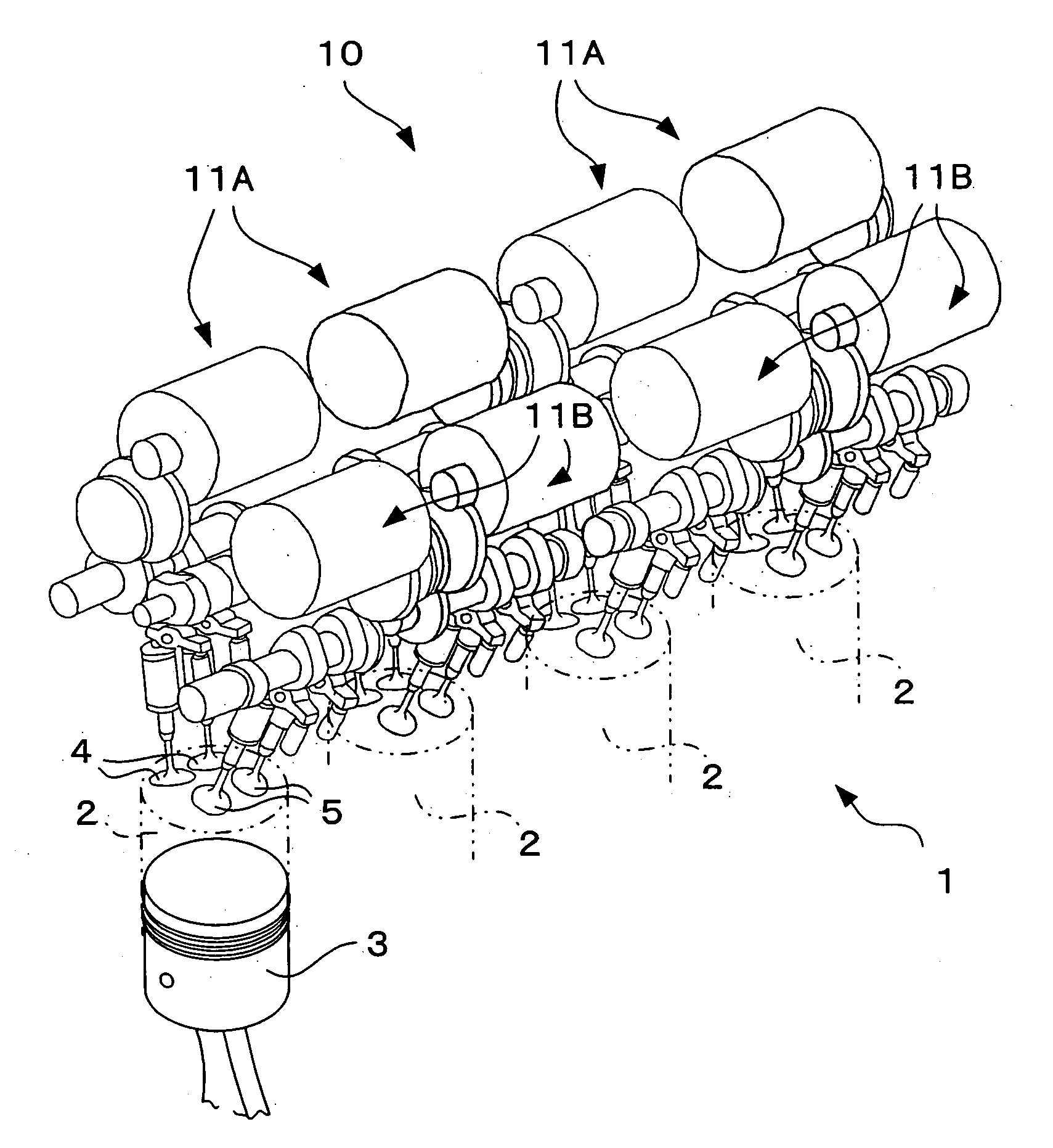
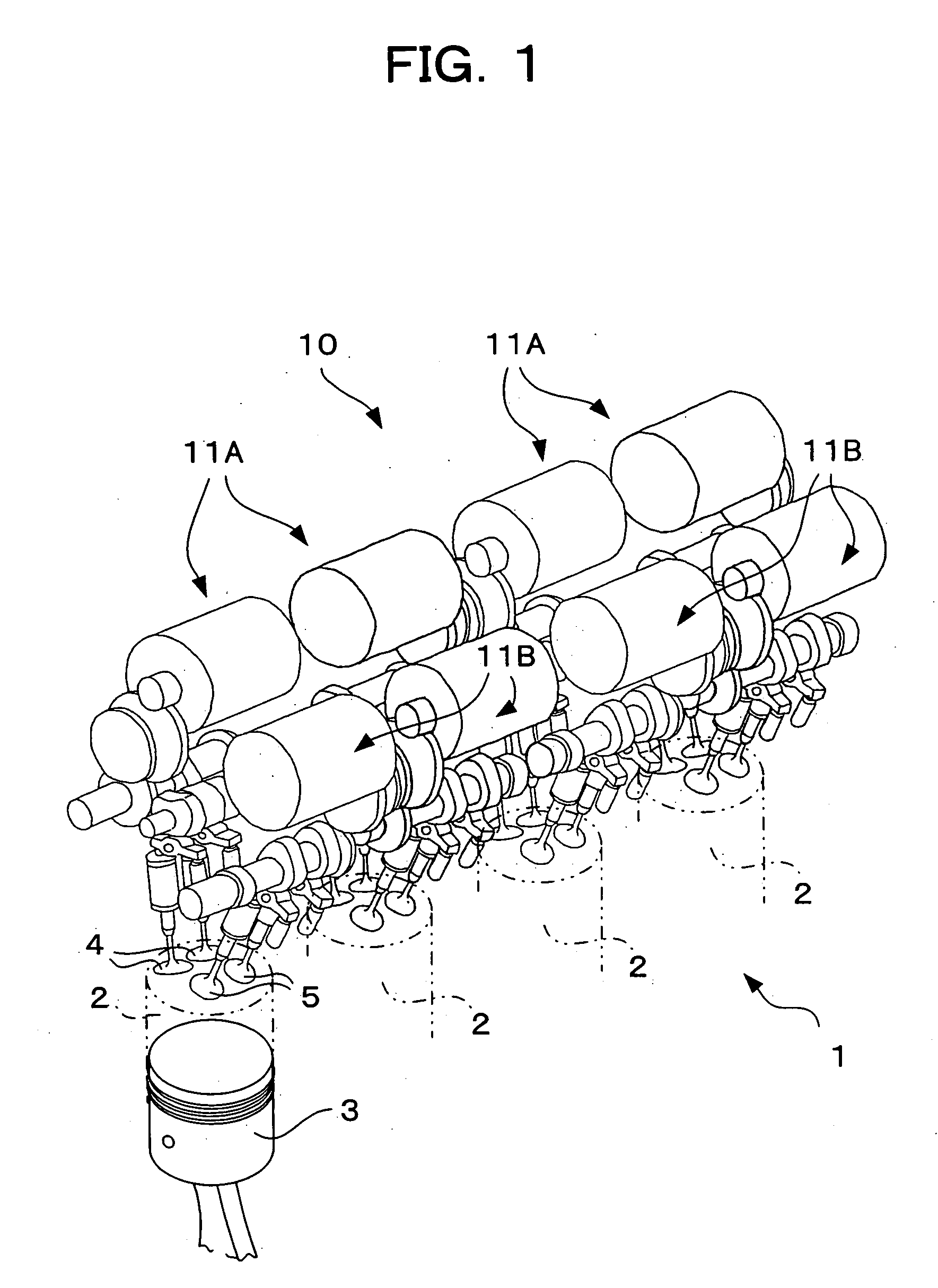
[0068] FIG. 1 shows an internal combustion engine 1 in which a valve-driving system according to the first embodiment of the present invention is incorporated. The internal combustion engine 1 is a multi-cylinder in-line gasoline engine. In the engine, a plurality of (four in FIG. 1) cylinders 2 . . . 2 are arranged in one direction, and pistons 3 are mounted in the respective cylinders 2 such that the pistons 3 can move vertically. Two intake valves 4 and two exhaust valves 5 are provided above each cylinder 2. These intake valves 4 and exhaust valves 5 are opened and closed by a valve-driving system 10 in association with vertical motion of the piston 3, thereby drawing air into the cylinder 2 and exhausting air from the cylinder 2.

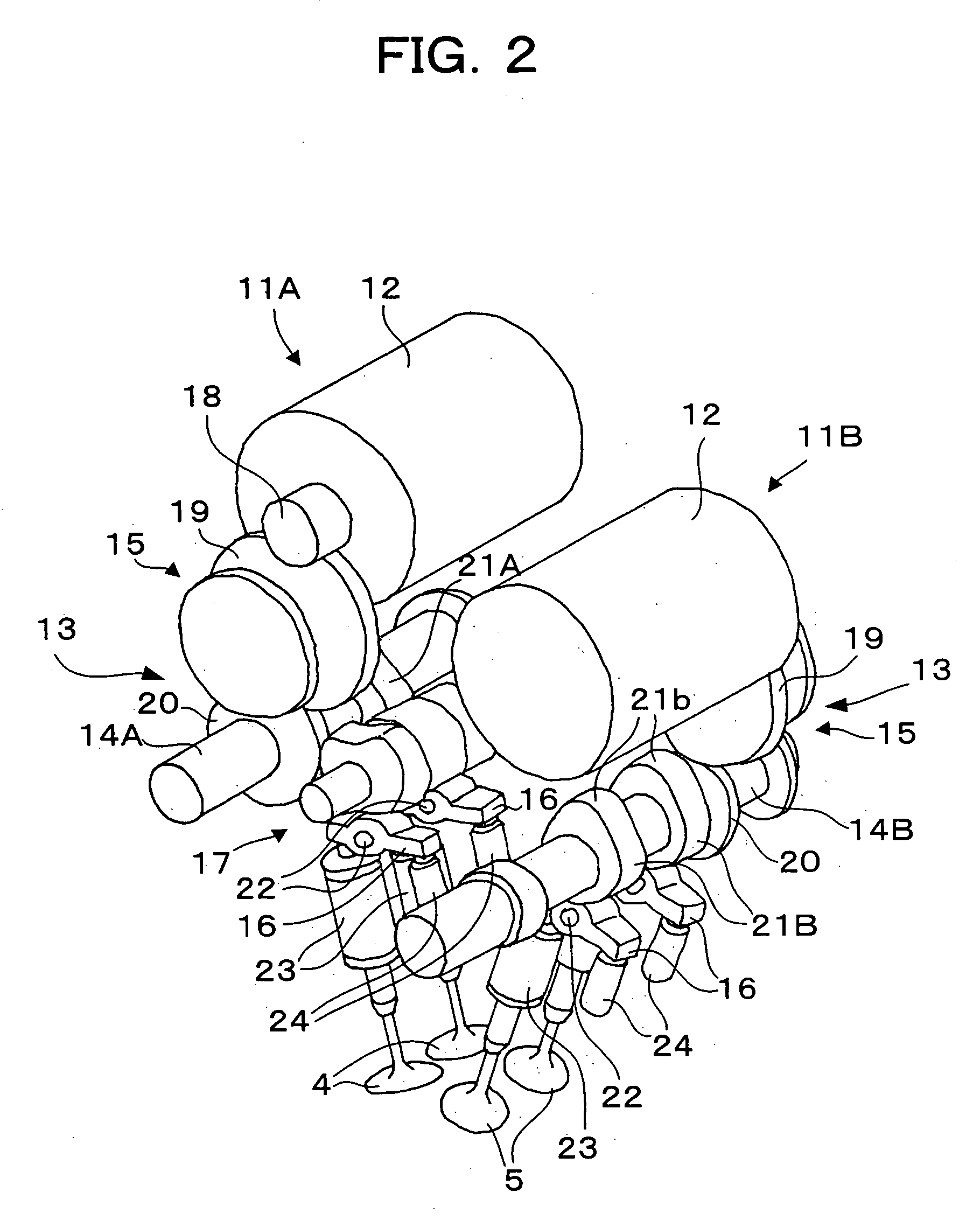
[0069] The valve-driving system 10 includes valve-driving apparatuses 1A. A provided on an intake-side of each cylinder 2 one each, and valve-driving apparatuses 11B. 11B provided on an exhaust-side of each cylinder 2 one each. ...

second embodiment

[0129] [Second Embodiment]

[0130] FIGS. 18A and 18B and 19A to 19C show a valve-driving apparatus 11C according to the second embodiment of the present invention. This valve-driving apparatus 11C drives the intake valve 4 or the exhaust valve 5 utilizing a link. An example for driving the intake valve 4 will be explained here, but the same structure may be used for driving the exhaust valve 5.

[0131] The valve-driving apparatus 11C includes the electric motor 12 as a driving source, and a power transmission mechanism 100 which converts the rotation motion of the motor 12 into the opening and closing motion of the intake valve 4. The power transmission mechanism 100 includes an eccentric plate 101 as a rotation member which is rotated by the motor 12, a first link 103 which is rotatably connected to a connection position which is eccentric from the rotation center of the eccentric plate 101 through a connection pin 102, and a second link 105 which is rotatably connected to an upper end...

third embodiment

[0138] [Third Embodiment]

[0139] FIGS. 20A, 20B and 20C show a valve-driving apparatus 11D according to the third embodiment of the present invention. This valve-driving apparatus 11D also drives the intake valve 4 or the exhaust valve 5 utilizing a link. Here, the valve-driving apparatus 11D drives the intake valve 4, but the same structure can be employed for driving the exhaust valve 5. In FIGS. 20A, 20B and 20C, the same members as those of the valve-driving apparatus 11D shown in FIGS. 18A and 18B are designated with the same reference signs.

[0140] The valve-driving apparatus 11D shown in FIGS. 20A, 20B and 20C includes the electric motor 12 as a driving source, and a power transmission mechanism 110 which converts the rotation motion of the motor 12 into the opening and closing motion of the intake valve 4. The power transmission mechanism 110 includes the eccentric plate 101 which is rotated by the motor 12, a first link 111 rotatably connected, through a connection pin 102, t...


PUM


Abstract

A valve-driving system which is applied to an internal combustion engine having a plurality of cylinders for driving an intake or exhaust valve provided in each cylinder, including a plurality of valve-driving apparatuses provided for driving valves of different cylinders of the internal combustion engine, wherein each valve-driving apparatus includes an electrical motor as a driving source for generating rotation motion; and a power transmission mechanism for converting the rotation motion of the electric motor into opening and closing motion of the valve to be driven and for transmitting the opening and closing motion to the valve through a cam or a link.

Description

BACGROUND OF THE INVENTION[0001] 1. Field of the Invention[0002] The present invention relates to a valve-driving system for driving an intake valve or an exhaust valve of an internal combustion engine.[0003] 2. Description of the Related Art[0004] An intake valve or an exhaust valve of a conventional internal combustion engine is opened and closed by power taken out from a crank shaft of an internal combustion engine. In recent years, however, an attempt has been made to drive the intake valve or the exhaust valve by means of an electric motor. For example, Japanese Patent Application Laid-open No. 8-177536 discloses a valve-driving apparatus which drives a cam shaft by a motor to open and close the intake valve for driving an EGR valve, and there is also known a valve-driving apparatus which converts rotation of a motor into a straight opening and closing motion of the valve utilizing a screw mechanism provided on a valve stem (see JP-A No. 10-73178).[0005] Since the apparatus whi...

Claims


Application Information

Patent Timeline
Patent Type & Authority Applications(United States)
IPC IPC(8): F01L1/46F01L1/04F01L9/20F01L9/22F01L13/00F01L31/22F02D13/02F02F7/00F02M25/07
CPCF01L1/042F01L9/04F01L13/00F01L2009/0411Y02T10/18F01L2800/00F02D13/0207F02M25/0752F01L2105/00F02M26/01F01L2305/00Y02T10/12F01L9/22F01L9/20F02D13/02
Inventor EZAKI, SHUICHIASADA, TOSHIAKITSUJI, KIMITOSHIKUSAKA, YASUSHIKATAOKA, KENJI
Owner TOYOTA JIDOSHA KK
Why Eureka
Try Eureka