Exhaust gas bellows expansion joint

a technology of expansion joints and exhaust gas, which is applied in the direction of fluid pressure sealing joints, pipe supports, pipe elements, etc., can solve the problems of reducing the efficiency of exhaust gas turbochargers, large overall length, and limited applicability of exhaust gas bellows expansion joints described her

Active Publication Date: 2007-10-23
ROLLS ROYCE SOLUTIONS GMBH
View PDF22 Cites 28 Cited by
  • Summary
  • Abstract
  • Description
  • Claims
  • Application Information

AI Technical Summary

Benefits of technology

[0005]The object of the present invention is to provide an exhaust gas bellows expansion joint for joining a first section and a second section of an exhaust pipe of an internal combustion engine with an exhaust gas turbocharger, which compensates thermal expansion and positional misalignment of the exhaust pipe.
[0007]The invention makes it possible for lateral misalignments of the exhaust pipe to be compensated by the exhaust gas bellows expansion joint. The first corrugated pipe for conveying the exhaust gas is protected against excessive temperatures by the protective sleeve. The protective sleeve and the air gap effectively prevent heat loss from the exhaust gas. The simple design of the exhaust gas bellows expansion joint allows inexpensive manufacture.
[0008]In accordance with one embodiment of the invention, it is proposed that the first corrugated pipe and the second corrugated pipe have a first, uniformly corrugated region and a second, nonuniformly corrugated region. The first, uniformly corrugated region is located, for example, immediately adjacent to the flanges, and the second region is located in the middle section of the exhaust gas bellows expansion joint. This embodiment achieves the advantage that the exhaust gas bellows expansion joint has a lower weight, so that the possibility of stimulation of vibrations is reduced.

Problems solved by technology

This results in a large overall length.
The exhaust gas bellows expansion joint described here has only limited applicability for an internal combustion engine with exhaust gas turbochargers, since energy is extracted from the exhaust gas by the cooling.
This reduces the efficiency of an exhaust gas turbocharger.

Method used


Image

  • Exhaust gas bellows expansion joint
  • Exhaust gas bellows expansion joint
  • Exhaust gas bellows expansion joint

Examples


Embodiment Construction

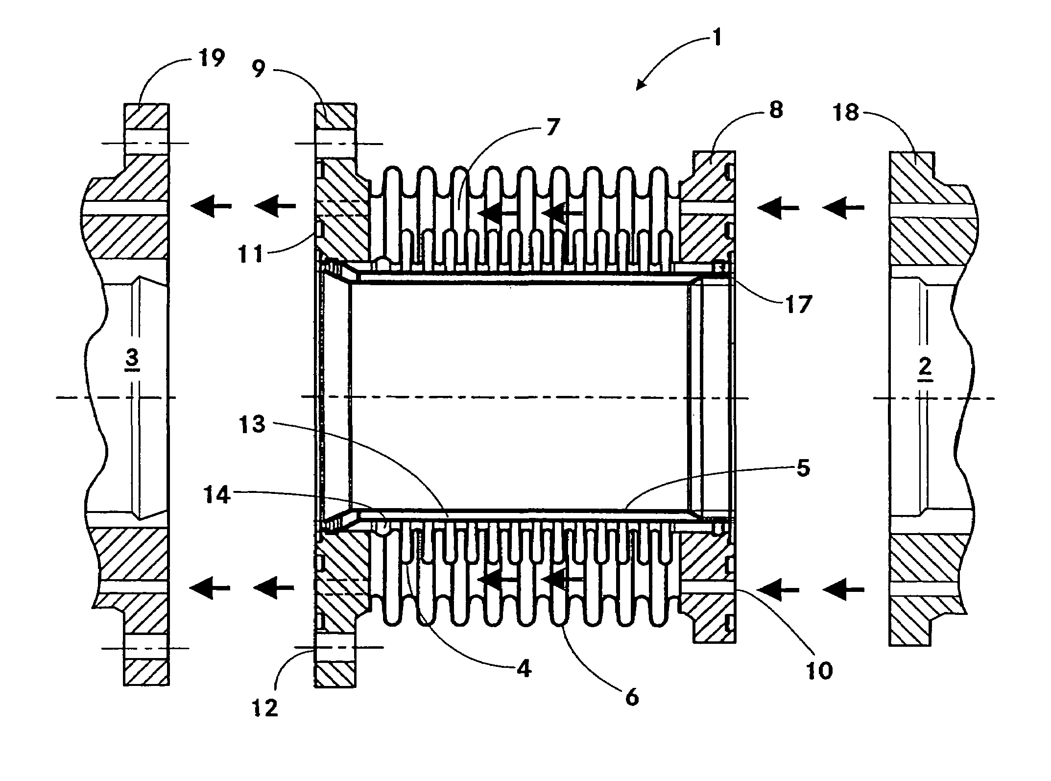
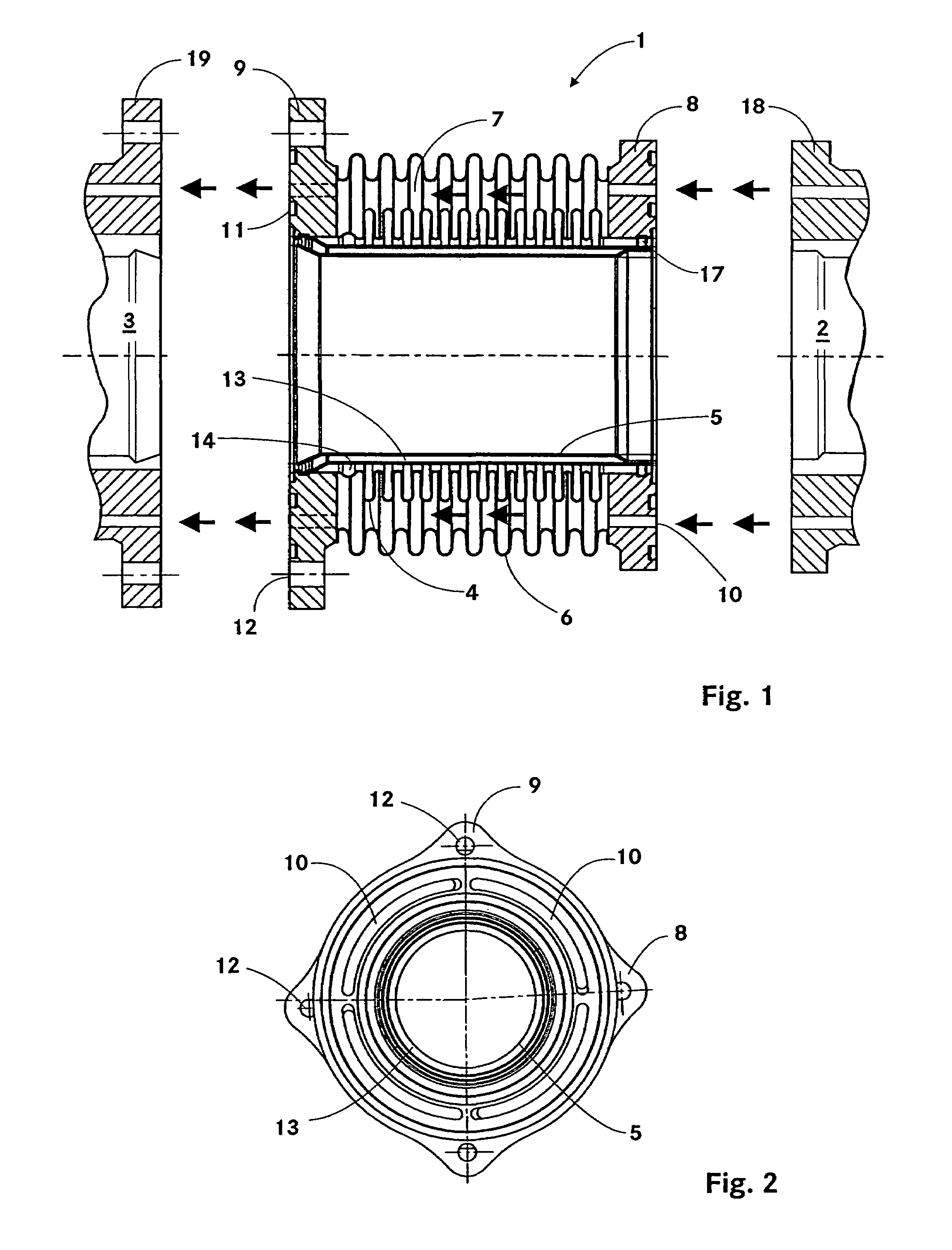
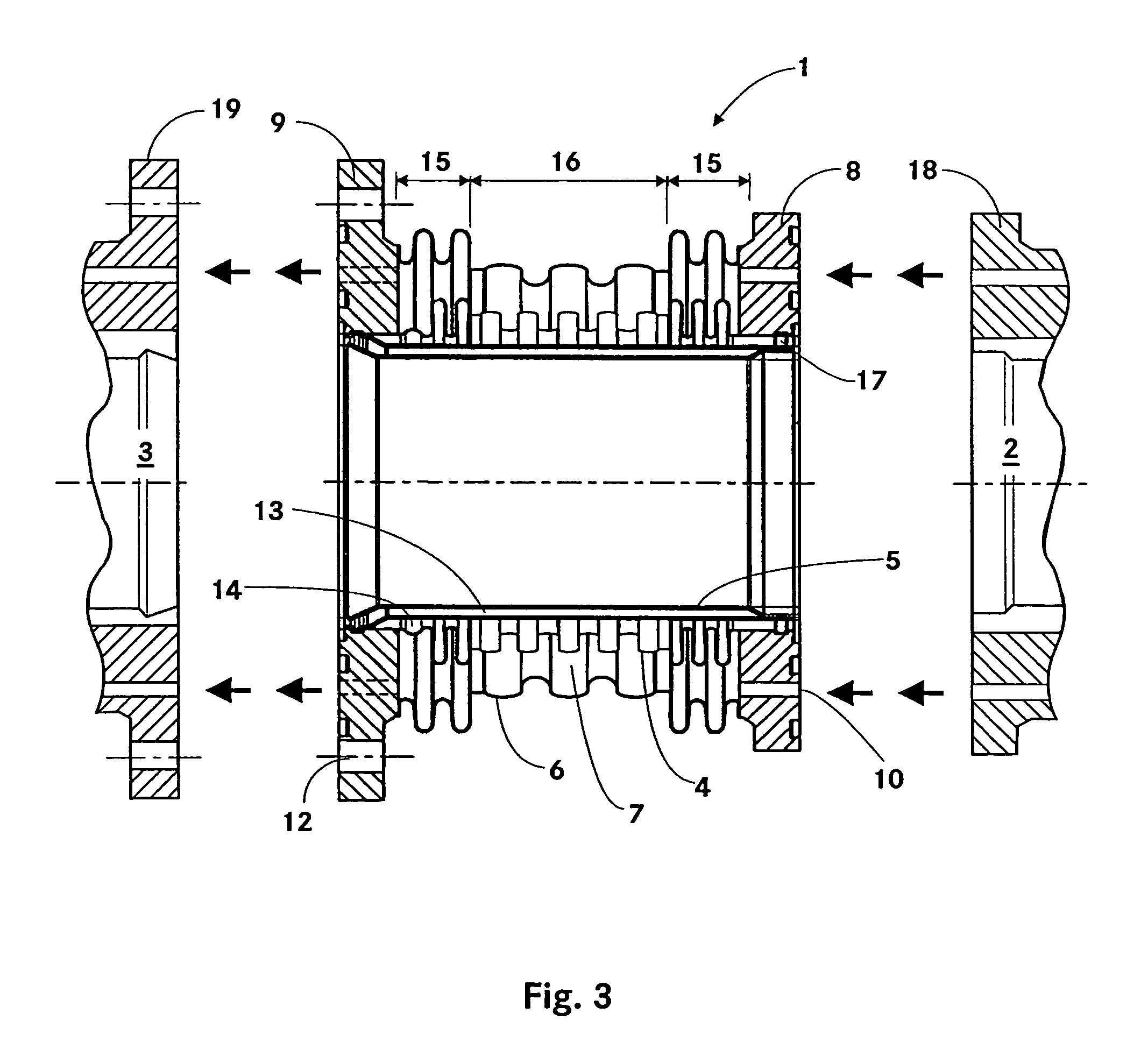
[0013]FIG. 1 shows a sectional view of the exhaust gas bellows expansion joint. The exhaust gas bellows expansion joint 1 connects a first section 2 and a second section 3 of an exhaust pipe. The exhaust gases of the internal combustion engine are supplied to an exhaust gas turbocharger (not shown) through the exhaust pipe. The exhaust gas bellows expansion joint 1 is screwed (drill holes 12) to the respective sections of the exhaust pipe by means of a first flange 8 and a second flange 9. To seal the surfaces of the flanges from the exhaust pipe, grooves 11 for holding gaskets are provided. The gaskets arranged in the grooves are located in an area that has low temperatures. Other components of the exhaust gas bellows expansion joint 1 include a first corrugated pipe 4, a second corrugated pipe 6, and a protective sleeve 5. The second corrugated pipe 6 surrounds the first corrugated pipe 4 at a certain radial distance to form an annular space 7. The two corrugated pipes are welded ...


PUM


Abstract

An exhaust gas bellows expansion joint for joining a first section and a second section of an exhaust pipe. The exhaust gas bellows expansion joint including a first corrugated pipe for conveying exhaust gas through the joint, a protective sleeve, which is inserted in the first corrugated pipe, a second corrugated pipe, which coaxially surrounds the first corrugated pipe, and an annular space between the first corrugated pipe and the second corrugated pipe for the passage of liquid through the joint.

Description

BACKGROUND OF THE INVENTION[0001]The invention concerns an exhaust gas bellows expansion joint for joining a first section and a second section of an exhaust pipe.[0002]Those skilled in the art are familiar with the plain pipe joint for joining two sections of an exhaust pipe. In this type of pipe joint, a first section with a greater inside diameter is pushed over a second section. Due to the self-locking nature of the joint, additional fastening of the pipes to each other is not necessary. However, to ensure that self-locking occurs, it is necessary to provide suitably great overlapping of the sections. This results in a large overall length.[0003]DE 35 39 778 C1 describes an exhaust pipe which is surrounded by a water-cooled jacket. An air gap is provided between the exhaust pipe and the jacket for thermal insulation. The junction of a first section with a second section of the exhaust pipe is designed as a plain pipe joint. The water passage from a first jacket to a second jacke...

Claims


Application Information

Patent Timeline
Patent Type & Authority Patents(United States)
IPC IPC(8): F16L27/10F01N3/04F01N13/08F01N13/14F01N13/18
CPCF01N3/043F01N13/14F01N13/1816F01N13/1805Y02T10/20Y02T10/12F16L27/1004F16L27/11F16L39/04
Inventor BAUMANN, HERMANNHAUSKNECHT, JOSEF
Owner ROLLS ROYCE SOLUTIONS GMBH
Why Eureka
Try Eureka