Position measuring system

a technology of position measurement and measuring device, which is applied in the direction of converting sensor output, instruments, electric digital data processing, etc., can solve the problems the output of structural elements, and the structural size of structural components, and achieve the effect of increasing the structural size of the position measuring devi

Inactive Publication Date: 2006-04-18
DR JOHANNES HEIDENHAIN GMBH
View PDF20 Cites 16 Cited by
  • Summary
  • Abstract
  • Description
  • Claims
  • Application Information

AI Technical Summary

Benefits of technology

[0010]It is therefore an object of the present invention to disclose a method for the functional control of a position measuring system which can be simply performed and which does not, or only negligibly, increase the structural size of the position measuring device.

Problems solved by technology

A high degree of functional dependability increases in importance in all types of usage, since faulty operations can cause considerable damage.
This step has the disadvantage that a redundant scanning unit is required, which increases the structural size and the output for structural elements.
The disadvantage of this step lies in the provision of mechanical stops and the provision of an additional drive mechanism, which considerably increase the structural size.

Method used


Image

  • Position measuring system
  • Position measuring system
  • Position measuring system

Examples


Embodiment Construction

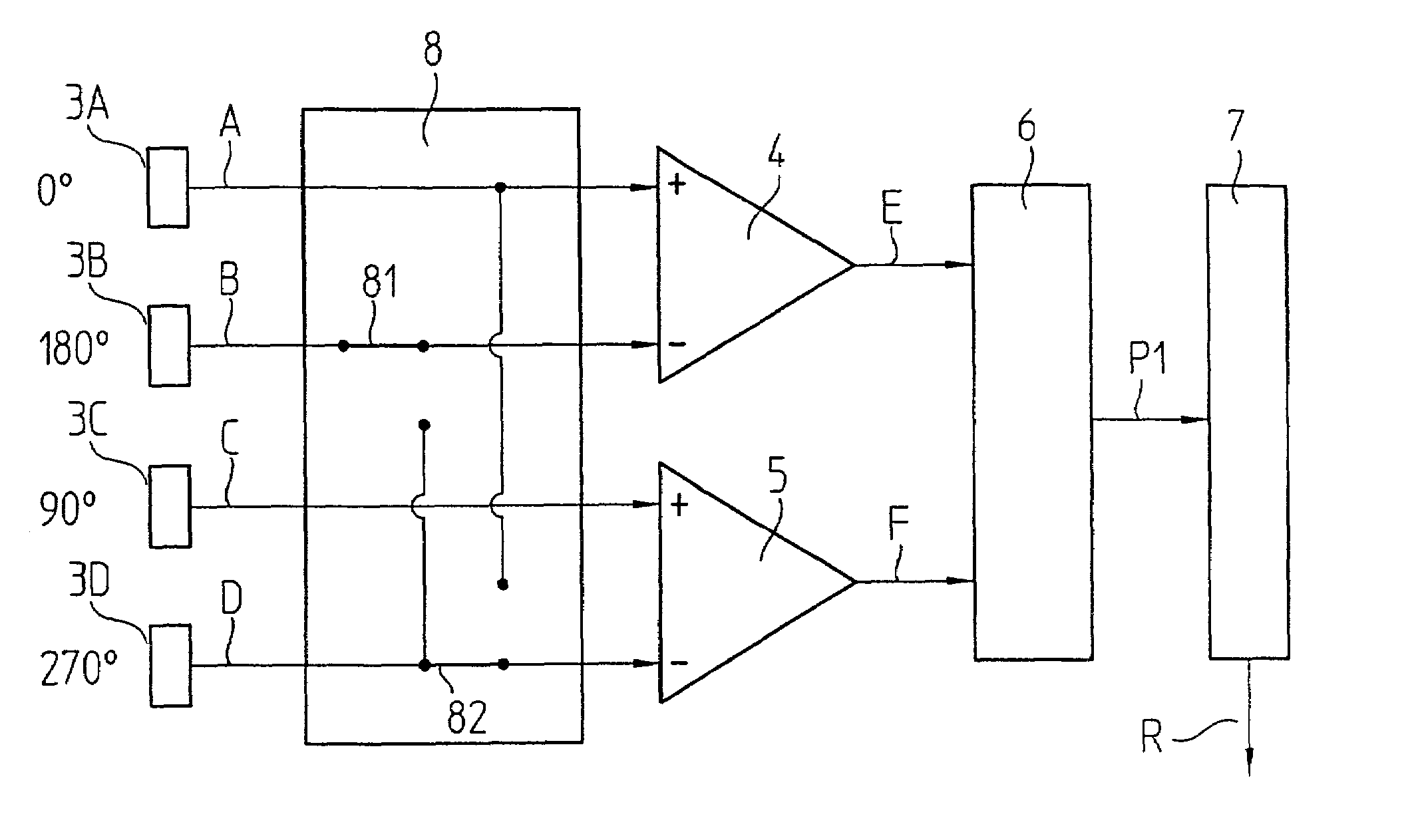
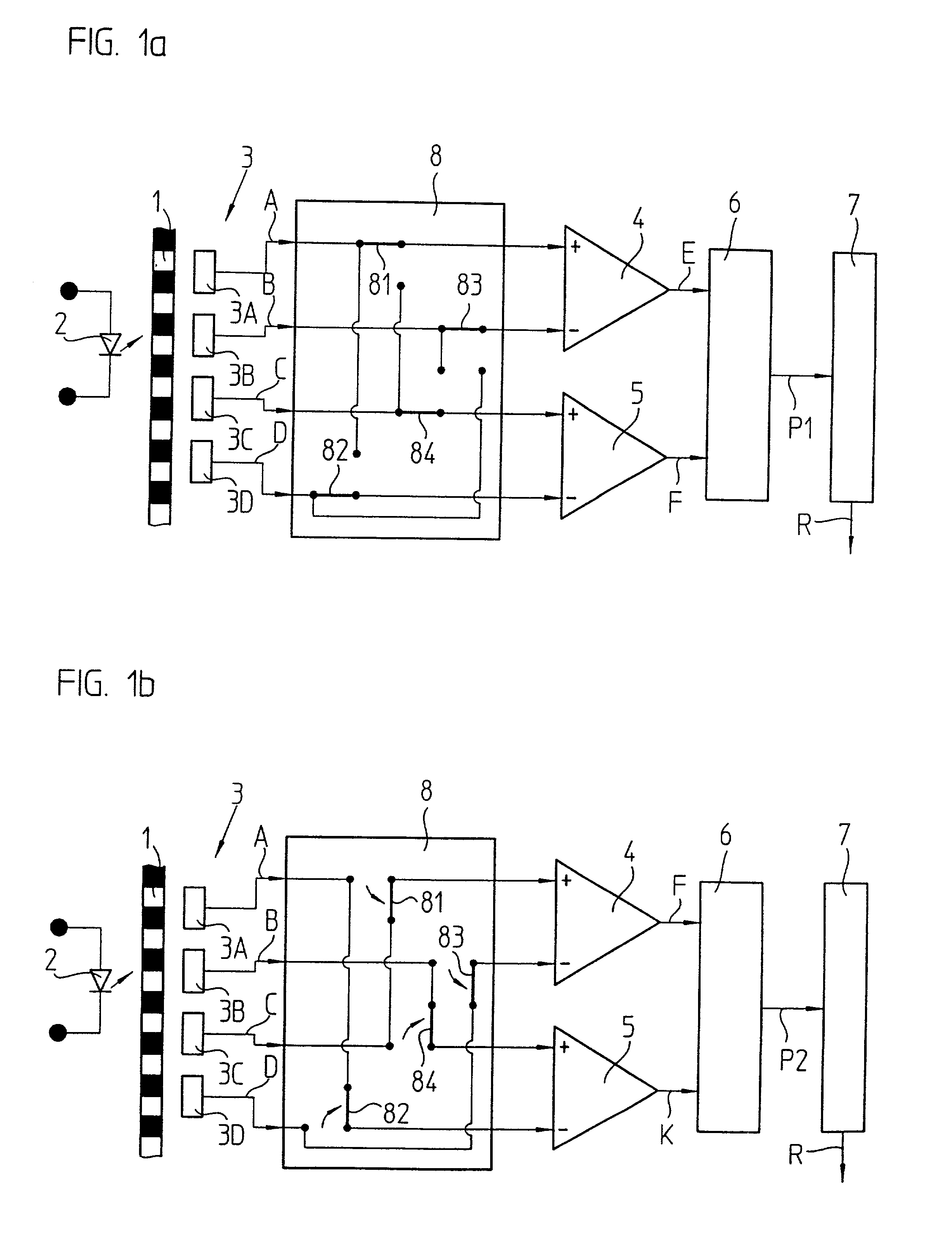
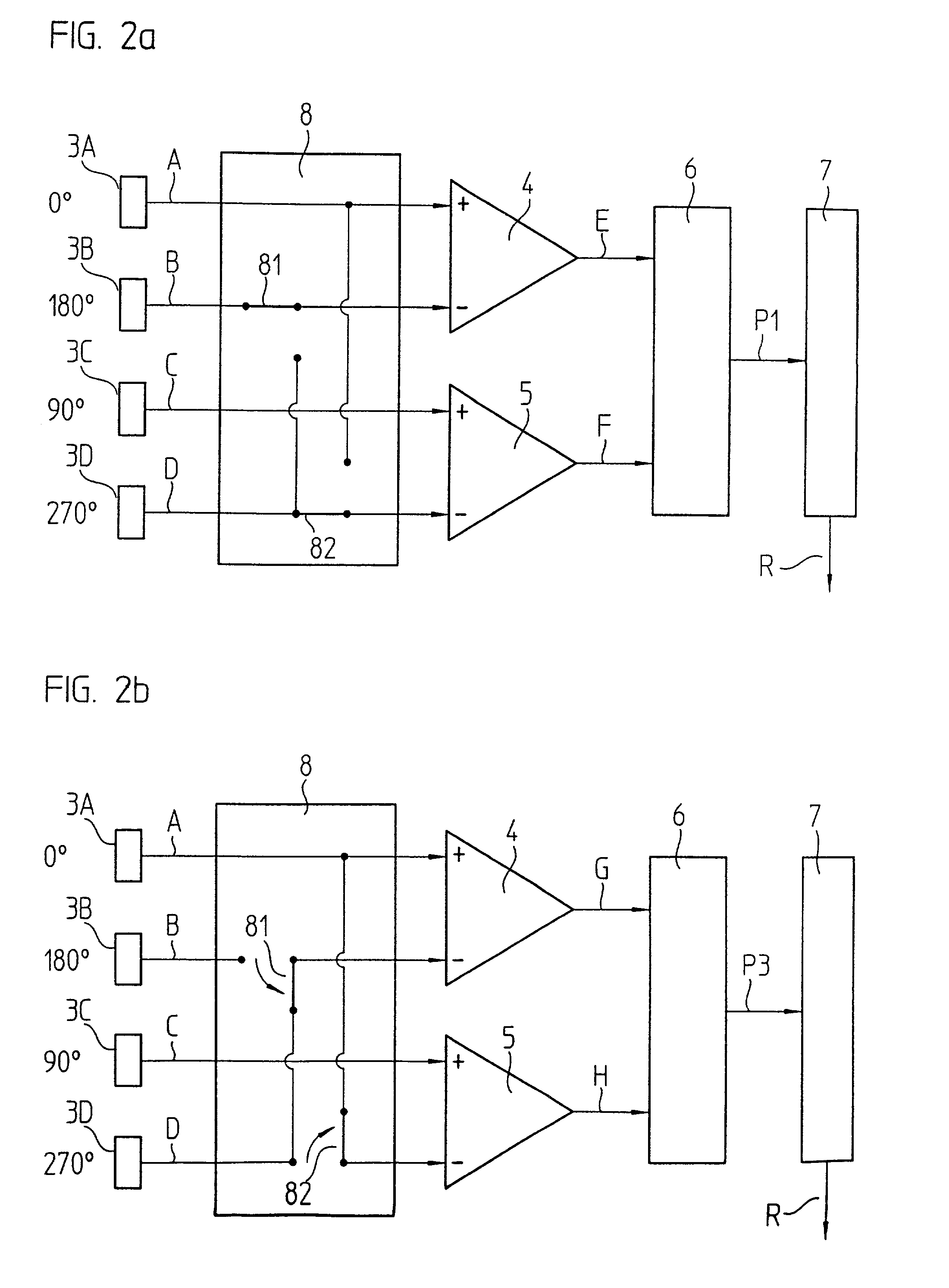
[0020]A first exemplary embodiment of the present invention is represented in FIGS. 1a and 1b. The position measuring system includes a photoelectrically scannable graduation 1, which is illuminated by light generated by a light source 2. The graduation 1 is scanned by a scanning unit 3 that is displaced relative to the graduation 1. During its displacement, the scanning unit 3 generates position-dependent electrical scanning signals A, B, C, D. The graduation 1 has an incremental, i.e. a periodic, marking so that the light emitted by the light source 2 impinges, periodically modulated, on a detector system that includes detector elements 3A, 3B, 3C, 3D of the scanning unit 3, which are arranged offset with respect to each other, and analog sinusoidal scanning signals A=a+sin α, B=a−sin α, C=a+cos α, D=a−cos α are generated, wherein a is a d.c. component and α is an angular value that ranges from 0° to 360° and is proportional to the instantaneous position within a graduation period...


PUM


Abstract

A method for the functional control of a position measuring system that includes placing a scanning unit at a position with respect to a graduation, generating a first scanning signal and a second scanning signal during the displacing, forming a first measured position value, P1, in accordance with a first linkage rule that involves the first scanning signal and the second scanning signal and forming a second measured position value, P2, in accordance with a second linkage rule that involves the first scanning signal and the second scanning signal, wherein the first linkage rule differs from the second linkage rule. Comparing the first measured position value, P1, with the second measured position value, P2, and generating an error signal as a result of the comparing.

Description

[0001]Applicant claims, under 35 U.S.C. § 119, the benefit of priority of the filing date of Dec. 6, 2000 of a German patent application, copy attached, Ser. No. 100 60 572.9, filed on the aforementioned date, the entire contents of which is incorporated herein by reference. Applicant also claims, under 35 U.S.C. § 119, the benefit of priority of the filing date of Feb. 1, 2001 of a German patent application, copy attached, Ser. No. 101 04 373.2, filed on the aforementioned date, the entire contents of which is incorporated herein by reference.BACKGROUND OF THE INVENTION[0002]1. Field of the Invention[0003]The present invention relates to a method for the function control of a position measuring system with a scanning unit, which can be displaced with respect to a graduation, wherein the scanning unit has several detector elements and generates several scanning signals at an instantaneous relative position between the graduation and the scanning unit. The present invention also rela...

Claims


Application Information

Patent Timeline
Patent Type & Authority Patents(United States)
IPC IPC(8): H04N7/04
CPCG01D5/24461G01D5/00
Inventor STRASSER, ERICH
Owner DR JOHANNES HEIDENHAIN GMBH
Why Eureka
Try Eureka