Shock wave tunnel test device and test method

A test device and tunnel technology, applied in the field of shock tubes, can solve the problems of unsatisfactory and difficult to obtain high-pressure plane waves, and achieve the effect of simple structure

Active Publication Date: 2020-11-24
INST OF DEFENSE ENG ACADEMY OF MILITARY SCI PLA CHINA
View PDF9 Cites 5 Cited by
  • Summary
  • Abstract
  • Description
  • Claims
  • Application Information

AI Technical Summary

Problems solved by technology

At the same time, most of the existing shock tube technology uses high-pressure gas loading, and a small amount of explosives are used to implode loading, and the peak value of the plane wave generated is mostly below 1MP. It is difficult to obtain high-pressure plane waves, which cannot meet certain high-pressure wave tests. requirements

Method used


Image

  • Shock wave tunnel test device and test method
  • Shock wave tunnel test device and test method
  • Shock wave tunnel test device and test method

Examples


Embodiment 1

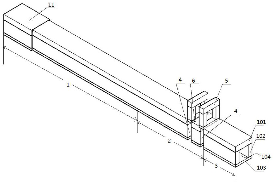
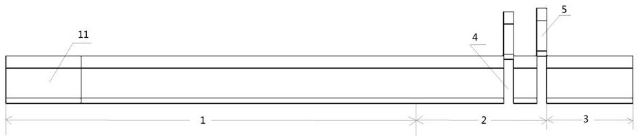
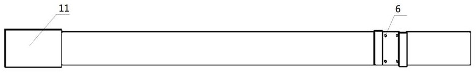
[0026] like figure 1As shown, the shock wave tunnel test device according to the preferred embodiment of the present invention adopts a reinforced concrete rectangular cylindrical structure, the two ends of the rectangular cylindrical structure are not closed, and the rectangular cylindrical structure is composed of a top plate 101, two side plates 102 and a bottom plate 103 , and form a tunnel 104 inside it, the shock tunnel test device includes: a planar shock wave forming section 1, which includes a head 11 arranged at one end of the shock wave tunnel test device, and the head 11 is used to receive the explosion shock wave generated by the explosive explosion. Wherein, the length of the planar shock wave forming section 1 is 30m, and the two side plates 102 of the head 11 of the planar shock wave forming section 1 are thickened to prevent the head from being damaged by the initial high pressure shock wave formed by the explosion. The thickness of the two side plates 102 of ...

Embodiment 2

[0030] In a preferred embodiment, the thickness of the movable concrete prefabricated frame 5 is slightly less than the width equal to the draw-in groove 4, the movable concrete prefabricated frame 5 is a hollow structure, and the outer frame cross-sectional size of the movable concrete prefabricated frame 5 is equal to that of the shock wave tunnel test device. Cross-sectional size, the cross-sectional size of the inner frame of the movable concrete prefabricated frame 5 is equal to the cross-sectional size of the tunnel 104 . When the concrete prefabricated test component or the movable concrete prefabricated frame 5 is vertically inserted into the slot 4, a gap of 2 cm is left between both sides of the slot 4 and the concrete prefabricated test component or the movable concrete prefabricated frame 5 to prevent hoisting difficulty. Wherein, when the movable concrete prefabricated frame 5 is hoisted in the two clamping slots 4, it is used for shock wave biological damage test...

Embodiment 3

[0041] The present invention also provides a shock tunnel test method comprising the following steps: placing the explosive at a certain distance from the outside of the head 11 of the plane shock wave forming section 1 of the above-mentioned shock tunnel test device; The concrete prefabricated test components or the movable concrete prefabricated frame 5 are hoisted directly in the two slots 4 at the end of the test section 2, and a plurality of pressure sensors are buried in the tunnel roof 101 and the two side plates 102; The generated high-pressure explosion shock wave enters the tunnel 104 from the head 11, and is reflected multiple times on the tunnel side wall of the remaining part of the plane shock wave forming section 1 and propagates forward; when the explosion shock wave moves to the tunnel 30m and forms a stable plane When the shock wave enters the test section; in the test section 2, the explosion shock wave develops into a plane shock wave that meets the test req...


PUM

PropertyMeasurementUnit
thicknessaaaaaaaaaa
thicknessaaaaaaaaaa
thicknessaaaaaaaaaa

Abstract

The invention discloses a shock wave tunnel test device. The shock wave tunnel test device adopts a reinforced concrete rectangular cylindrical structure, and a tunnel is formed in the structure, theshock wave tunnel test device comprises: a plane shock wave forming section, which includes a head arranged at one end of the shock wave tunnel test device and used for receiving explosive shock wavesgenerated by explosive explosion, wherein the length of the plane shock wave forming section is 30m; a tail section, which is arranged at the other end of the shock wave tunnel test device, and is anexplosive shock wave outflow section; and a test section, which is located between the plane shock wave forming section and the tail section, wherein stable planar shock waves are formed when the explosive shock waves reach the test section; and two clamping grooves are vertically formed in the tail part of the test section, are arranged at an interval, and are used for hoisting a concrete prefabricated test component or directly hoisting a movable concrete prefabricated frame. The shock wave tunnel test device is simple in structure, relatively low in manufacturing cost and capable of meeting various test requirements.

Description

technical field [0001] The invention relates to the technical field of shock tubes, in particular to a shock tunnel test device and a test method. Background technique [0002] The development and application of shock tube technology has a history of more than 100 years. It is widely used in the fields of weapon explosion effects, aerodynamics, and aeroacoustics. Recently, it has begun to play a role in the research of gas lasers, environmental science, and energy science. , and produced a variety of new test devices such as shock wave wind tunnels. The shock tube is usually a long cylindrical tube with both ends closed, consisting of a high-pressure air chamber and a low-pressure air chamber, separated by a diaphragm. Generally, the high-pressure loaded shock tube is filled with pure hydrogen or helium of several to tens of pressures in the high-pressure chamber, and filled with several millimeters of mercury or tens of millimeters of mercury in the low-pressure chamber. ...

Claims


Application Information

Patent Timeline
Patent Type & Authority Applications(China)
IPC IPC(8): G01M7/08G01M99/00G01N3/313G01N3/02
CPCG01M7/08G01M99/007G01N3/313G01N3/02G01N2203/001G01N2203/0067G01N2203/0258G01N2203/0676
Inventor 胡金生章毅罗丹刘云飞高伟亮徐翔云张磊
Owner INST OF DEFENSE ENG ACADEMY OF MILITARY SCI PLA CHINA
Why Eureka
Try Eureka