Small flow control valve

A technology for controlling valve and small flow, applied in the direction of lift valve, valve detail, valve device, etc., to achieve the effect of large scaling factor, effective drive, and improved control accuracy and sensitivity

Active Publication Date: 2017-05-31
CHINA PETROLEUM & CHEM CORP +1
View PDF6 Cites 3 Cited by
  • Summary
  • Abstract
  • Description
  • Claims
  • Application Information

AI Technical Summary

Problems solved by technology

[0009] In order to solve the problem of stable control of small flow rate under the condition of high pressure difference, the present invention p...

Method used


Image

  • Small flow control valve
  • Small flow control valve

Examples


Embodiment Construction

[0048] The present invention will be further described below in conjunction with the accompanying drawings and implementation examples.

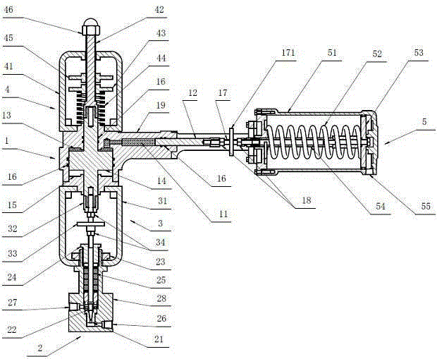
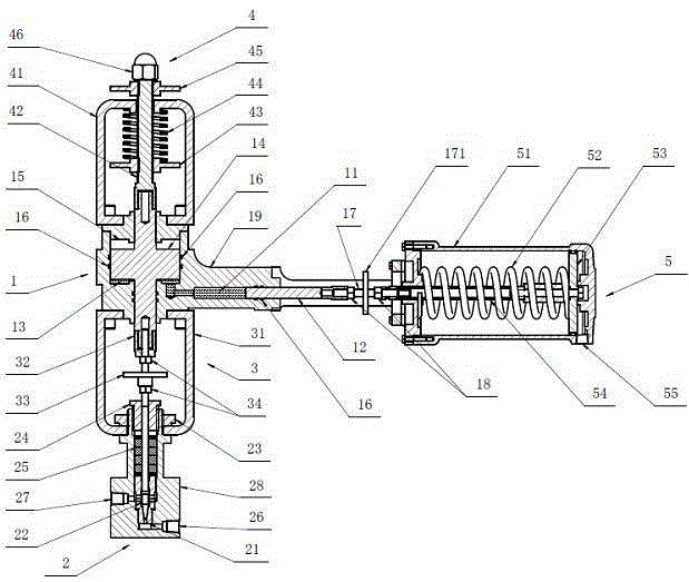
[0049] like figure 1 As shown, the small flow control valve of the present invention includes five parts: a hydraulic mechanism 1 , a reset device 4 , a valve connection device 3 , a valve 2 and an actuator 5 . The hydraulic mechanism 1 includes an integral frame 19, and two mutually perpendicular hydraulic cylinders are arranged in the integral frame 19, namely the active hydraulic cylinder 11 and the slave hydraulic cylinder 13, and the active hydraulic cylinder 11 and the slave hydraulic cylinder 13 respectively. They are connected by a channel inside the overall frame, the active piston 12 is arranged in the active hydraulic cylinder 11, and the driven piston 14 is arranged in the slave hydraulic cylinder 13; the whole frame cover is arranged at the open end of the slave hydraulic cylinder 15; The sectional area of ​​the active hydrauli...


PUM


Abstract

The invention discloses a small flow control valve which can be used in rigorous conditions. The small flow control valve comprises five parts, namely a hydraulic mechanism, a reset device, a valve connecting device, a valve body and an actuator. The hydraulic mechanism is composed of a whole rack, an active piston, a slave piston and an actuator connecting device. The valve body adopts a conventional high-pressure valve structure provided with an adjusting type valve rod, and a valve element adopts a long conical valve needle and a valve seat. The actuator adopts a general piston type actuator with a long stroke. According to the flow valve, stable control over micro-flow can be realized through extremely tiny opening change, and precise control over the micro-flow under a high pressure difference is achieved. Meanwhile, the control valve further has the characteristics of open structure, flexible configuration, convenient conversion and convenient maintenance and adjustment.

Description

technical field [0001] The invention relates to a small flow control valve, in particular to a control valve suitable for small flow control under the condition of high pressure difference. Background technique [0002] At present, there are many small and micro experimental devices that operate under high pressure conditions, such as hydrogenation, Fischer-Tropsch synthesis, coal liquefaction, high-pressure polymerization, etc. The operating pressure is usually 10-20MPa, and some are even under ultra-high pressure conditions of more than 100MPa. run under. The processing capacity of these high-pressure experimental devices is very small. For example, a hydrogenation experimental device with a catalyst loading of 200 ml usually has a processing capacity of about 100 mL / hr. It has always been a difficult problem to discharge the process products continuously and smoothly under such severe conditions of high pressure difference and small flow rate. [0003] The small flow co...

Claims


Application Information

Patent Timeline
IPC IPC(8): F16K1/00F16K31/143
CPCF16K1/00F16K31/143
Inventor 王群
Owner CHINA PETROLEUM & CHEM CORP
Why Eureka
Try Eureka