Spotlight

a technology of spotlights and spotlights, applied in the field of spotlights, can solve the problems of poor operability and difficulty in adjusting the position of each lens of focusing, and achieve the effect of poor operability and simple performan

Active Publication Date: 2005-12-29
MARUMO ELECTRIC
View PDF5 Cites 16 Cited by
  • Summary
  • Abstract
  • Description
  • Claims
  • Application Information

AI Technical Summary

Benefits of technology

[0006] Therefore, according to such a structure, since the screw pitches of the gear and the rack engaged with the gear are the same as each other and the distance between the lenses generated by rotating the handle is determined by the screw pitch, it is difficult to associate the position of each lens of which the focusing is adjusted with the position of the lens of which the zoom is adjusted. Accordingly, in the case in which the zoom adjustment is made after the focus adjustment is made, the position of the image formation is changed. Thereby, the focusing should be adjusted again and thus the operability thereof is poor.
[0007] The present invention is made in consideration of the above-mentioned problems, and it is an object of the present invention to provide a novel spotlight capable of simply performing the focus adjustment and the zoom adjustment without changing the position of the image formation although the zoom adjustment is made after the focus adjustment is made, in the spotlight for performing the focus adjustment and the zoom adjustment by sliding at least two lenses which are arranged in the lamp body forward and backward along the optical axis.

Problems solved by technology

Therefore, according to such a structure, since the screw pitches of the gear and the rack engaged with the gear are the same as each other and the distance between the lenses generated by rotating the handle is determined by the screw pitch, it is difficult to associate the position of each lens of which the focusing is adjusted with the position of the lens of which the zoom is adjusted.
Thereby, the focusing should be adjusted again and thus the operability thereof is poor.

Method used


Image

  • Spotlight
  • Spotlight
  • Spotlight

Examples


Embodiment Construction

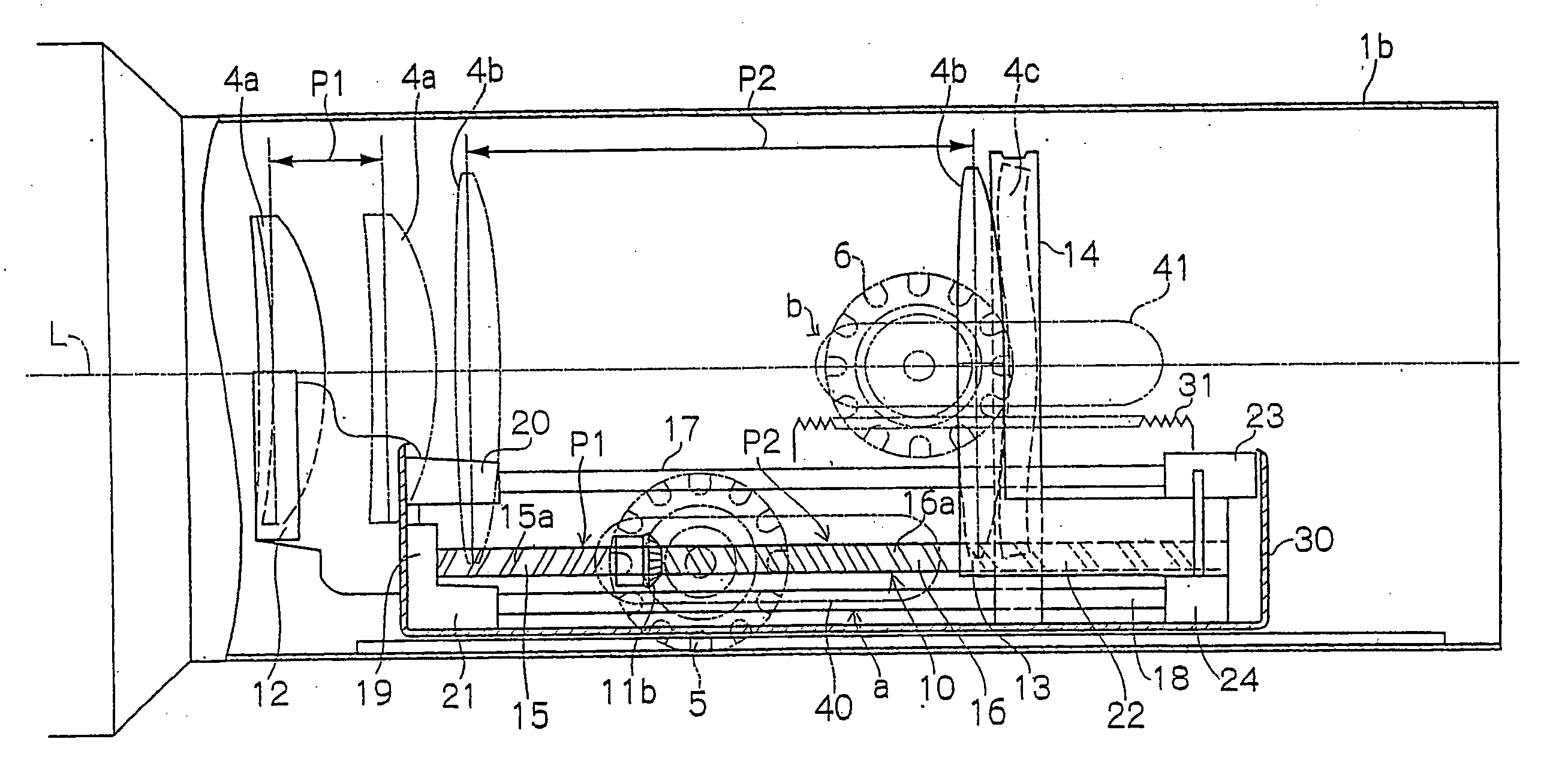
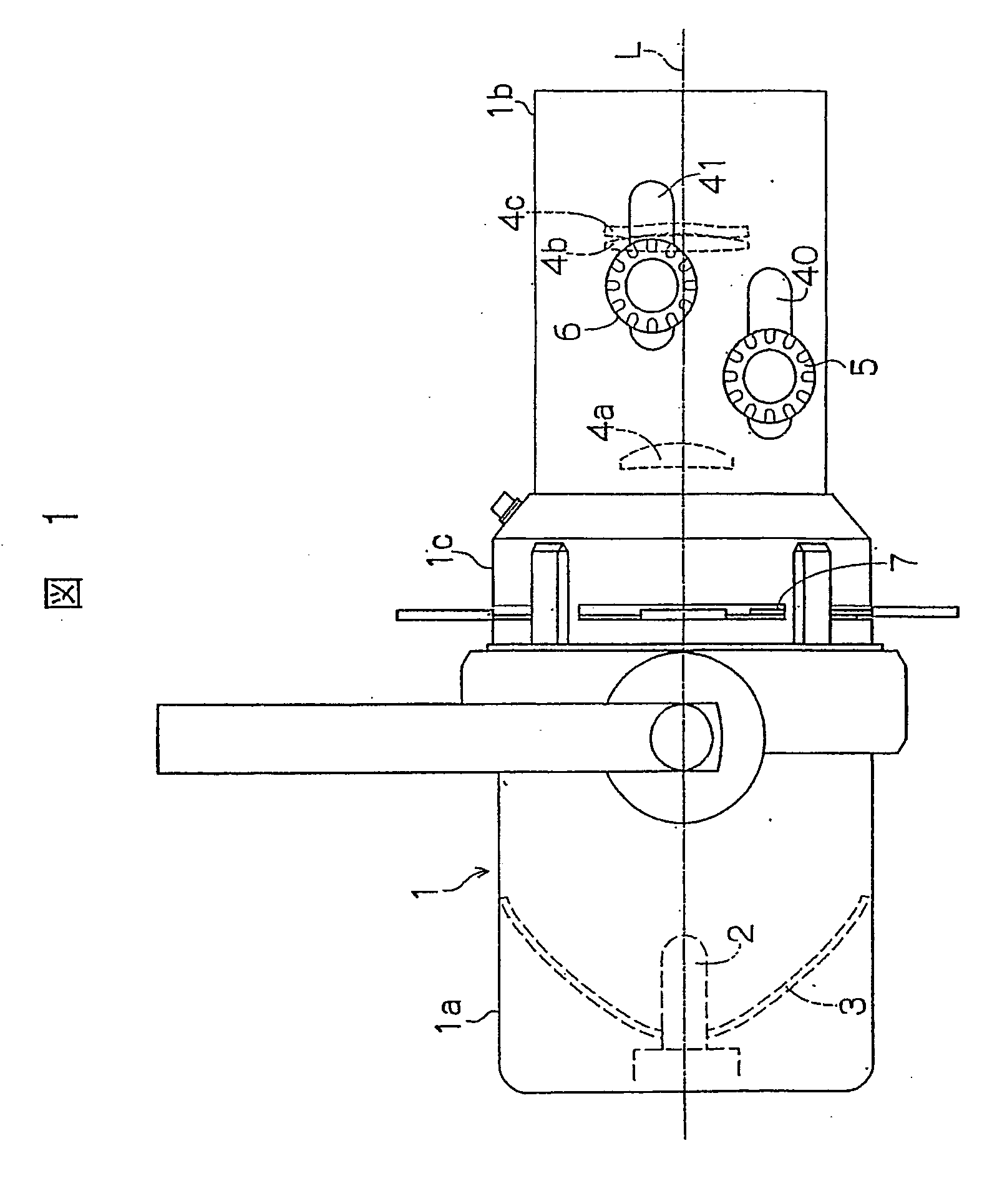
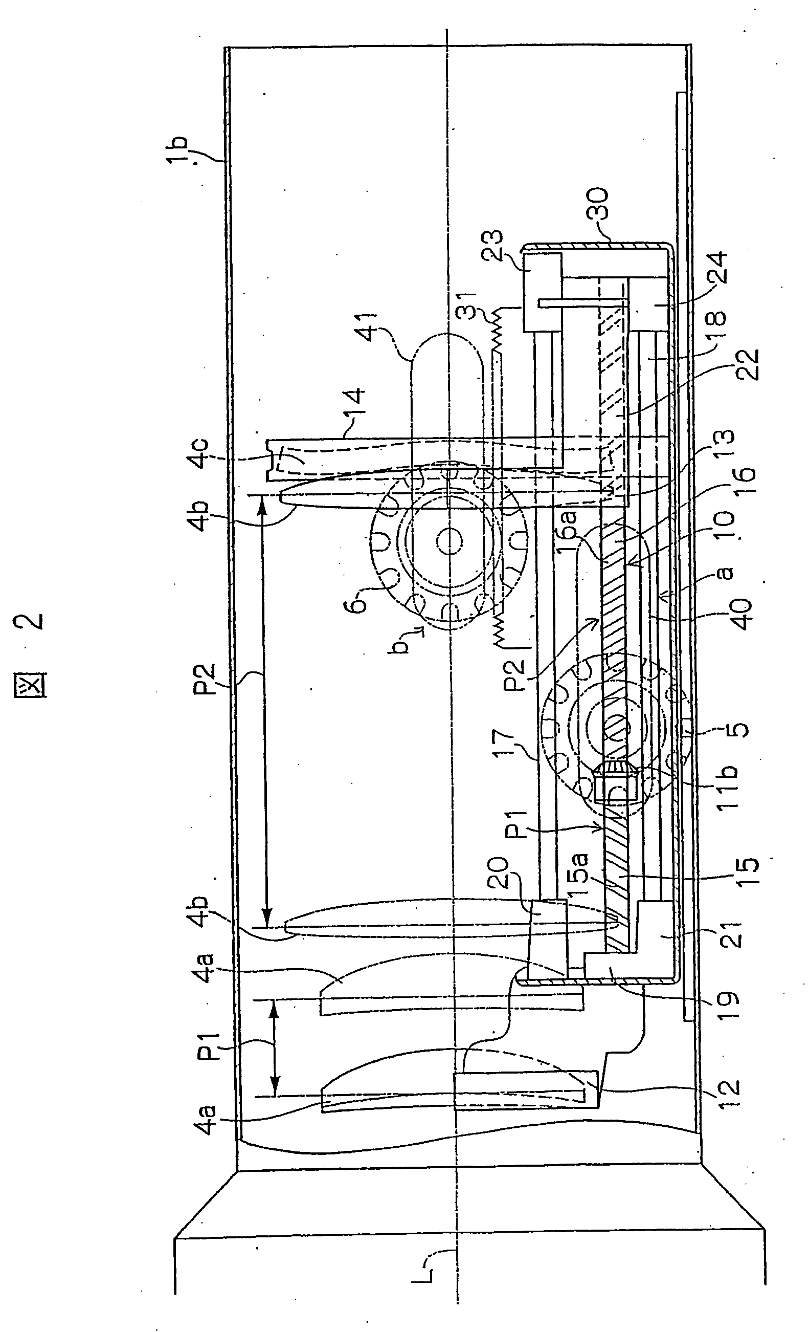
[0028] Hereinafter, an embodiment of a spotlight according to the present invention will be described with reference to FIGS. 1 to 6. FIG. 1 is a side view showing a schematic structure of the spotlight A of the present embodiment. In FIG. 1, 1 is a lamp body, 2 is a light source, 3 is a reflector, 4a, 4b, and 4c are lenses, 5 is a zoom adjustment handle, 6 is a focus adjustment handle, and L is an optical axis.

[0029] In the lamp body 1, a cutter frame 1c accommodating a needed numbers of cutter blades 7 for cutting the light passing through an aperture in an any frame shape is arranged between a lamp housing section la accommodating the light source 2 and the reflector 3 and the lens barrel section 1b accommodating the lenses 4a, 4b and 4c. In the lens barrel section 1b, a zoom adjustment mechanism a for adjusting the distance between the lens 4a, the lens 4b and the lens 4c to adjust the size of the projected image and a focus adjustment mechanism b for adjusting the distance bet...


PUM


Abstract

A novel spotlight where the position of image formation does not change even when the zoom adjustment is made after focus adjustment, so that focus adjustment and zoom adjustment can be facilitated. When a drive shaft (10) is rotated by operating a zoom adjustment handle (5), a lens (4a) moves forward and backward according to an unequal pitch (P1) of a first screw section (15), and a lens (4b) moves forward and backward according to an equal pitch (P2) of a second screw section (16), so that the distances between the lenses (4a-4c) are changed and zoom adjustment is made. Focusing adjusted by a focus adjustment mechanism (b) does not change even when the distances between the lenses are changed. Therefore, focus adjustment and zoom adjustment can be made extremely simply, and the spotlight can be used particularly useful in performance space such as TV studios and theater stages.

Description

TECHNICAL FIELD [0001] The present invention relates to the improvement of a spotlight used in performance space, such as TV studios and theater stages, and more particularly, to a spotlight in which a light source, a reflector and at least two lenses are arranged in a lamp body, and which comprises a focus adjustment function for adjusting the distance between each of the lenses and the light source to adjust the focus of a transmitted light (the position of image formation) and a zoom adjustment function for adjusting the distances between the lenses to adjust the size of the projected image (the spread angle of the transmitted light). BACKGROUND ART [0002] As a mechanism for performing a focus adjustment or a zoom adjustment in such a spotlight, there is a mechanism which a first lens and a second lens provided in a lens barrel of the lamp body are supported along the optical axis by a first lens holder and a second lens holder so as to be slid forward and backward, respectively,...

Claims


Application Information

Patent Timeline
Patent Type & Authority Applications(United States)
IPC IPC(8): F21S8/00F21S2/00F21S10/00F21V14/00F21V14/06F21V17/02F21W131/406F21Y101/00G02B7/10
CPCF21V14/06G02B7/10F21W2131/406F21V17/02
Inventor TANAKA, TSUNEMICHIISHIZONE, TSUTOMU
Owner MARUMO ELECTRIC
Why Eureka
Try Eureka