Moving image display device and method for moving image display

a technology of moving image and display device, which is applied in the field of moving image display device and moving image display method, can solve the problems of flicker (blinking) occurring on the overall screen, flicker occurring only in the moving object part, and feeling stress while viewing, so as to suppress the flicker of moving image

Inactive Publication Date: 2007-05-03
SEIKO EPSON CORP
View PDF10 Cites 16 Cited by
  • Summary
  • Abstract
  • Description
  • Claims
  • Application Information

AI Technical Summary

Benefits of technology

[0010] For one aspect of the present invention, the purpose is to suppress moving image flicker using a method that is simpler than in the past, and that displays smooth moving images.

Problems solved by technology

In the past, when displaying images on a moving image display device such as a CRT, television or the like with a refresh rate of less than 60 Hz, there were cases when flicker (blinking) occurred on the overall screen.
However, even when a sufficient refresh rate is secured, in cases when displaying moving images such as when a moving object moves on the screen, there were cases when flicker occurred only in the moving object part on the screen rather than on the overall screen.
This kind of phenomenon is not limited to CRTs and televisions, but is also seen in cases when displaying moving images on moving image display devices such as liquid crystal displays, plasma displays, projectors or the like, on the display unit of a PDA, mobile phone or the like, or on the screen in a movie theater or the like, and this was a problem common to moving image display.
There were cases when once the viewers became bothered by the existence of the moving image flicker described above, they felt stress while viewing.
However, with the prior art described above, because it is necessary to generate a completely new intermediate frame from two frame images, the calculation processing for this becomes huge, so it was difficult to improve the moving image display speed.
Also, to generate a completely new intermediate frame, it is necessary to secure a large frame memory capacity, and this became a factor in increasing costs.
Also, when switching the display method with moving images and still images, there was concern that smooth video image display would not be possible due to the occurrence of a virtual image during switching of the display method or the like.

Method used


Image

  • Moving image display device and method for moving image display
  • Moving image display device and method for moving image display
  • Moving image display device and method for moving image display

Examples


first embodiment

[0039] A. [0040] (A-1) Projector Hardware Constitution:

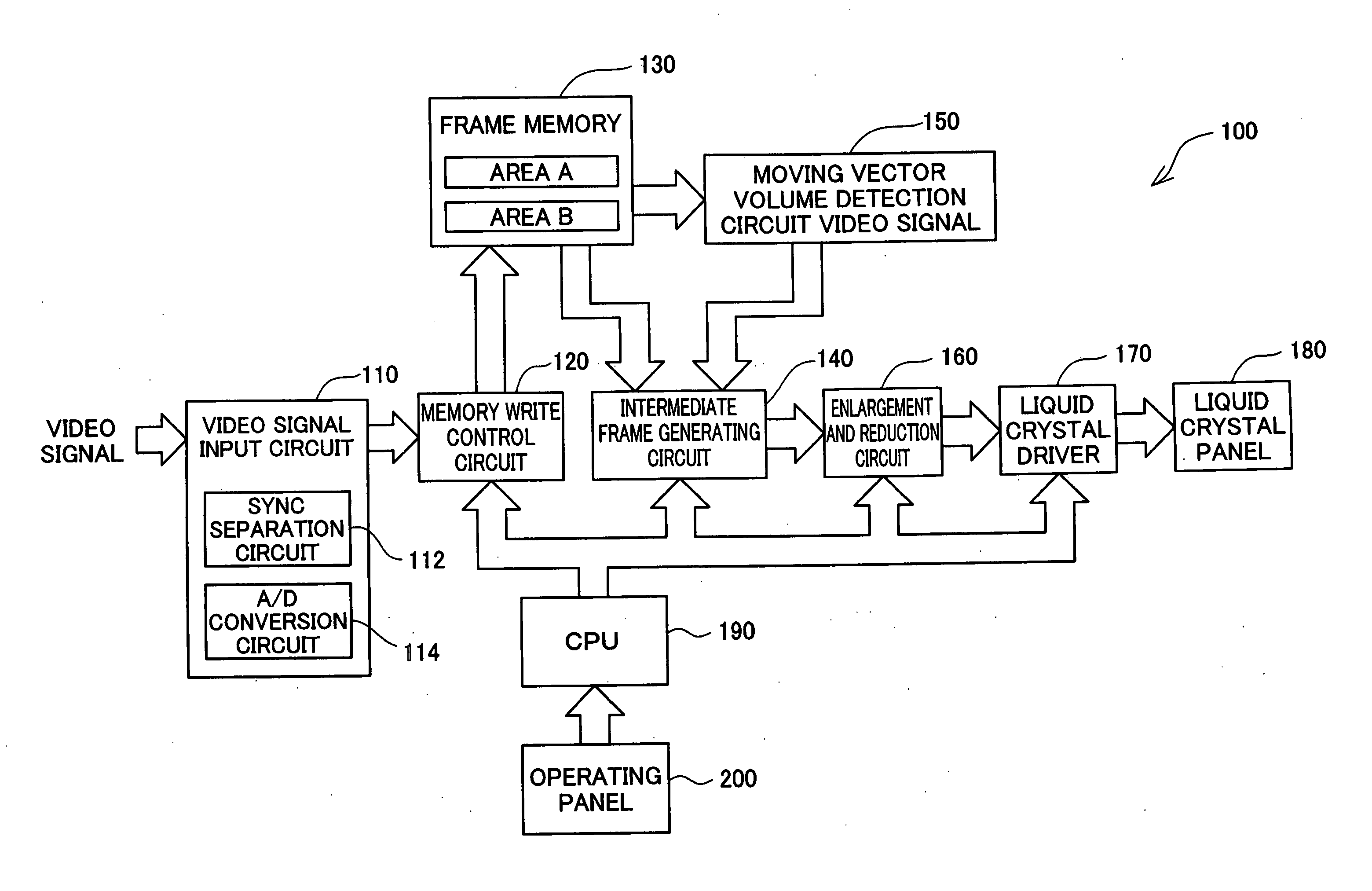
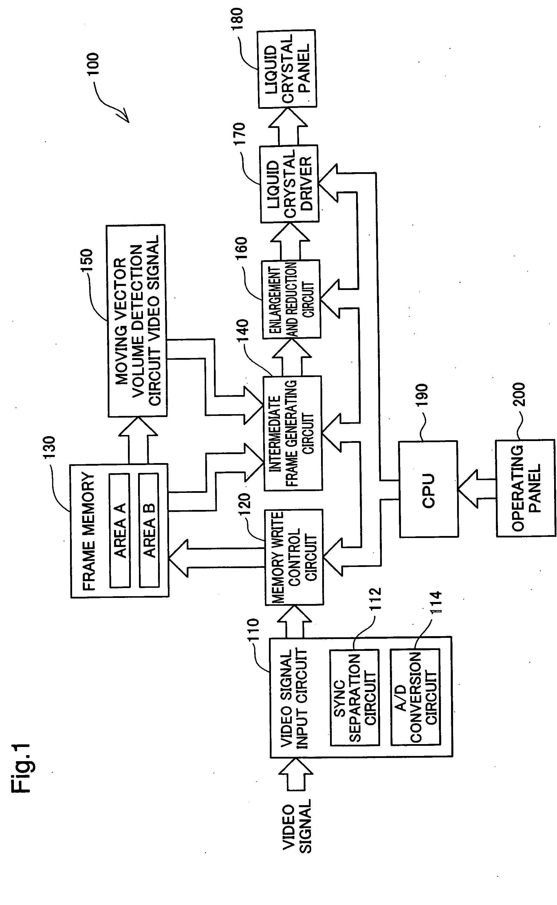
[0041]FIG. 1 is a block diagram showing the hardware constitution of the projector 100 as an embodiment of the moving image display device of the present invention. This projector 100 has a function of performing display of moving images by increasing by at least two times the frame rate of the original moving image. A detailed description will be given later regarding the specific constitution for performing display at two or more times the frame rate.

[0042] As shown in the drawing, the projector 100 of the present invention comprises a video signal input circuit 110, a memory write control circuit 120 connected to this video signal input circuit 110, a frame memory 130 connected to the memory write control circuit 120, a moving vector volume detection circuit 150 connected to the frame memory 130, the intermediate frame generating circuit 140 connected to the frame memory 130 and the moving vector volume detection circuit 1...

second embodiment

[0077] B.

[0078] With the first embodiment described above, described was a case when one intermediate frame image was generated and display of the moving image was performed at twice the frame rate of the original video image. In contrast to this, with the second embodiment, described is a case when two intermediate frame images are generated, and the moving image is displayed at a frame rate that is three times that of the original video image.

[0079]FIG. 7 is an explanatory drawing visually expressing the moving image formed on the liquid crystal panel 180 of the second embodiment. As shown in the upper level and middle level of the drawing, with this embodiment, the memory write control circuit 120 writes in sequence to the frame memory 130 the frame image data frame (N−1), frame (N), and frame (N+1), and the control circuit 250 performs five consecutive readings at a doubled cycle of the frame rate of the original video image. At this time, simultaneous reading is performed by a...


PUM

PropertyMeasurementUnit
brightnessaaaaaaaaaa
brightness coefficientaaaaaaaaaa
speedaaaaaaaaaa

Abstract

The synthesizing circuit inputs signals representing the brightness coefficient K2 and the brightness coefficient K3 from the multiplexer, and inputs the overscanned frame image data D1 in pixel units from the first latch circuit. When the start frame image read the third time and the after frame image read the first time are input simultaneously, the synthesizing circuit calculates the brightness coefficient K2 for the brightness value of the pixels of the start frame image, and calculates the brightness coefficient K3 for the brightness value of the pixel of the after frame image. Then, it synthesizes the pixels of the start frame image and the pixels of the after frame image for which the respective brightness coefficients were calculated, and generates the intermediate frame image data D2. As a result, it moving image flicker is suppressed using an easier method than in the past, and it is possible to realize smoother moving image display.

Description

CLAIM OF PRIORITY [0001] The present application claims priority from Japanese application P2005-314217A filed on Oct. 28, 2005, the content of which is hereby incorporated by reference into this application. BACKGROUND [0002] 1. Field of the Invention [0003] The present invention relates to technology for displaying moving images by consecutively displaying a plurality of frame images, and more specifically relates to technology for synthesizing a plurality of frame images and generating an intermediate frame image. [0004] 2. Description of the Related Art [0005] In the past, when displaying images on a moving image display device such as a CRT, television or the like with a refresh rate of less than 60 Hz, there were cases when flicker (blinking) occurred on the overall screen. However, even when a sufficient refresh rate is secured, in cases when displaying moving images such as when a moving object moves on the screen, there were cases when flicker occurred only in the moving ob...

Claims


Application Information

Patent Timeline
Patent Type & Authority Applications(United States)
IPC IPC(8): H04N7/01G02F1/133G09G3/20G09G3/36H04N5/66
CPCG09G3/2096G09G5/008G09G5/397G09G5/399G09G2320/0247G09G2320/0261G09G2320/106H04N7/0132H04N7/014H04N21/4825G09G3/20G09G3/36H04N5/66
Inventor TAKEUCHI, KESATOSHISAGAWA, TAKAHIROIISAKA, HIDEHITOINAZUMI, MITSUHIRO
Owner SEIKO EPSON CORP
Why Eureka
Try Eureka