Hybrid exhaust valve assembly

a technology of exhaust valve and hybrid valve, which is applied in the direction of water feed control, machines/engines, lighting and heating apparatus, etc., can solve the problems of performance and sound characteristics, additional expense resulting from diagnostics, and the active valve will normally remain in a fixed position

Active Publication Date: 2008-05-22
ARVIN TECH INC
View PDF4 Cites 17 Cited by
  • Summary
  • Abstract
  • Description
  • Claims
  • Application Information

AI Technical Summary

Benefits of technology

[0008]An exhaust valve assembly is capable of being both actively and passively actuated as needed to provide desired engine performance and sound characteristics. The exhaust valve assembly includes a flapper valve fixed to a valve shaft where the flapper valve is movable between a closed position, an intermediate position, and an open position. A resilient member biases the flapper valve toward the closed position. An electric actuator actively moves the flapper valve at least from the closed position to the intermediate position. A coupling mechanism couples the valve shaft to an electric actuator shaft and allows the flapper valve to move to the open position in response to exhaust flow sufficient to overcome a biasing force of the resilient member without requiring input from the electric actuator.

Problems solved by technology

Thus, the exhaust valve is closed at idle and low engine speeds in full cylinder mode, which may be undesirable in terms of engine performance and sound characteristics.
A disadvantage with active valves is that there is additional expense resulting from a need for diagnostics to sense error states.
An additional disadvantage is that an active valve will normally remain in a fixed position regardless of flow.

Method used


Image

  • Hybrid exhaust valve assembly
  • Hybrid exhaust valve assembly
  • Hybrid exhaust valve assembly

Examples


Embodiment Construction

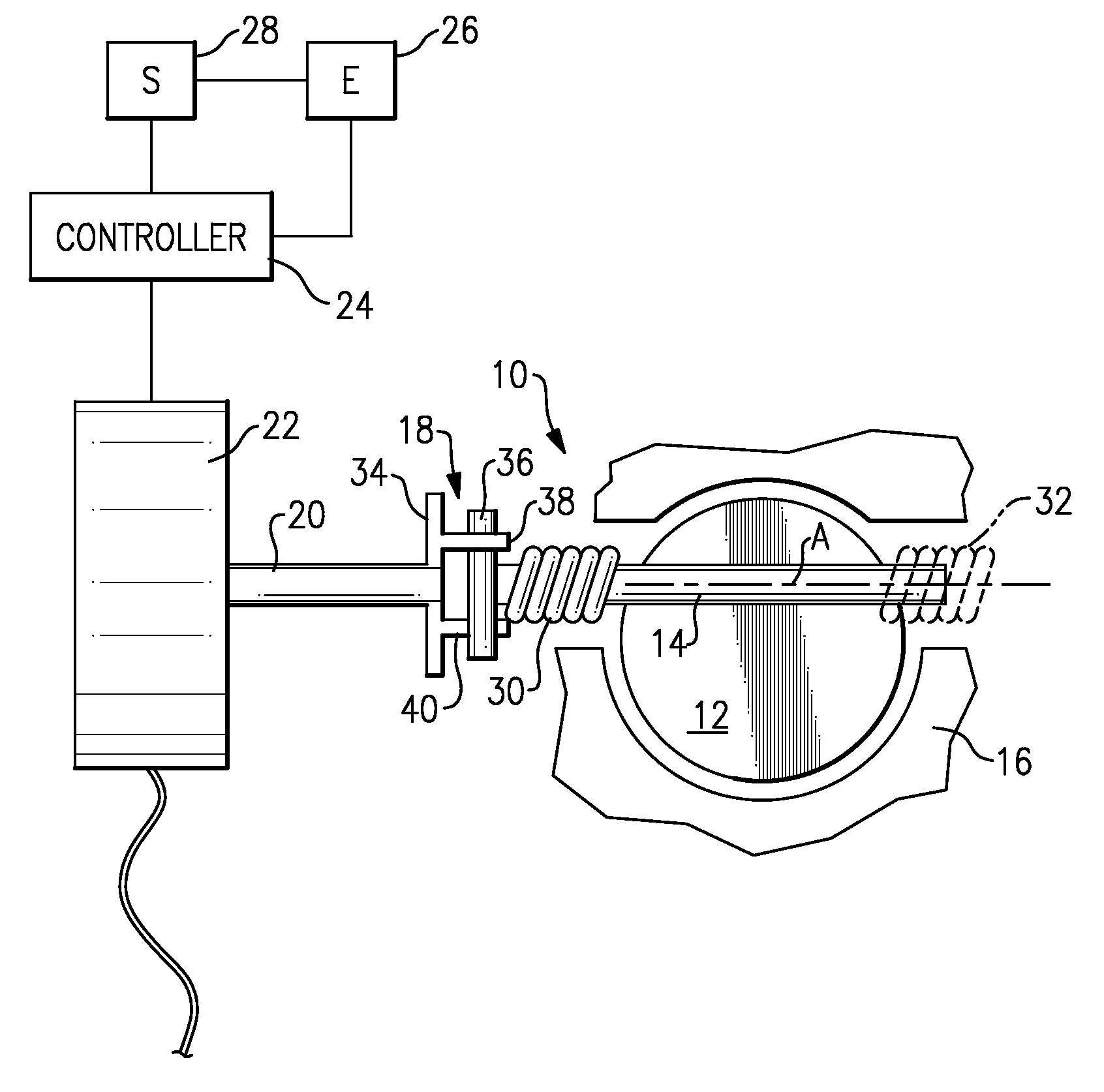
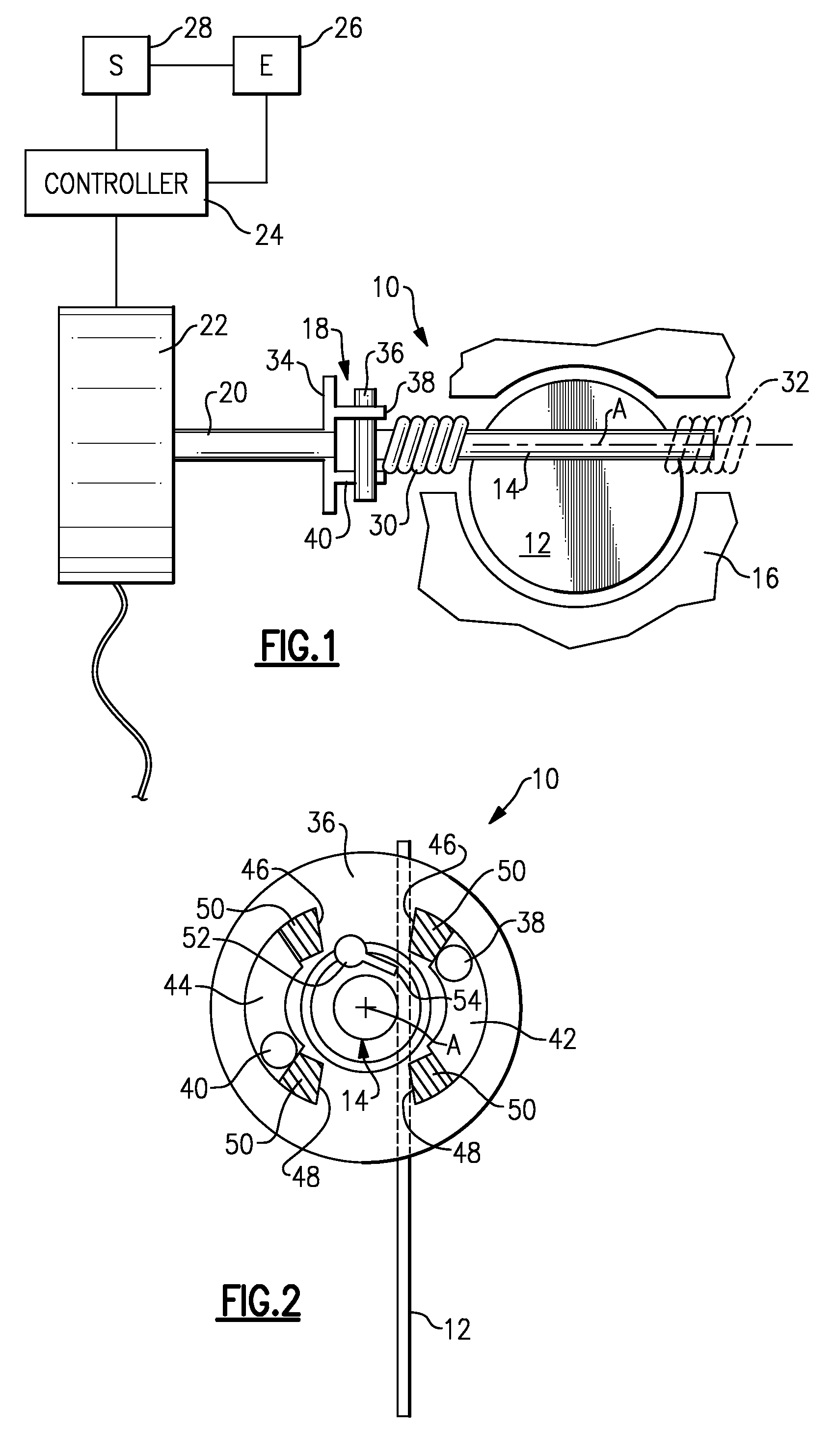
[0026]An exhaust valve assembly is shown generally at 10 in FIG. 1. The exhaust valve assembly 10 includes a flapper valve 12 that is fixed for rotation with a valve shaft 14. The valve shaft 14 is supported for rotation within, and relative to, an exhaust component housing 16 as known. The valve shaft 14 defines an axis of rotation A. A coupling mechanism 18 couples the valve shaft 14 to an actuator shaft 20 that is driven by an electric actuator 22. The electric actuator 22 can be an electric motor or other type of actuator. The flapper valve 12 is movable between a closed position, an intermediate position, and an open position. The flapper valve 12 is held fixed in these discrete positions under certain conditions. This will be discussed in greater detail below.

[0027]A controller 24 sends control signals to the electric actuator 22 to control movement of the flapper valve 12 according to desired specifications. The controller 24 receives information from an engine 26 via sensors...


PUM


Abstract

An exhaust valve assembly includes a flapper valve fixed to a valve shaft where the flapper valve is movable between a closed position, an intermediate position, and an open position. A resilient member biases the flapper valve toward the closed position. An electric actuator actively moves the flapper valve at least from the closed position to the intermediate position. A coupling mechanism couples the valve shaft to an electric actuator shaft and allows the flapper valve to move to the open position in response to exhaust flow sufficient to overcome a biasing force of the resilient member without requiring input from the electric actuator.

Description

RELATED APPLICATIONS[0001]This application is a continuation-in-part of U.S. application Ser. No. 11 / 602,924, filed Nov. 21, 2006.TECHNICAL FIELD[0002]The subject invention relates to a hybrid exhaust valve assembly that can be actuated actively or passively as needed.BACKGROUND OF THE INVENTION[0003]Some vehicle engines utilize cylinder deactivation technology, which deactivates one or more engine cylinders at lower engine speeds to provide desired engine performance and to optimize fuel economy, for example. Exhaust valve assemblies have been used in vehicle exhaust systems to attenuate exhaust noise in exhaust systems using cylinder deactivation technology.[0004]One type of exhaust valve that has been used is a spring loaded passive valve, which does not specifically respond to cylinder deactivation demands, but instead only operates depending upon exhaust flow rate. This type of “passive” valve is resiliently biased toward a closed position, and moves to an open position when ex...

Claims


Application Information

Patent Timeline
Patent Type & Authority Applications(United States)
IPC IPC(8): F01N7/00
CPCF01N13/08F16K31/041F16K1/222F02D9/04F16K1/221
Inventor WILLATS, ROBINCALLAHAN, JOSEPHABRAM, KWINKALYANASAMY, GOVINDARAJ
Owner ARVIN TECH INC
Why Eureka
Try Eureka